
English Manual
Page 16
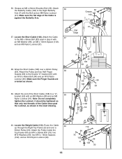
... the Double "U"-bracket (61) with an M10 x 46mm Bolt (84) and an M10 Nylon Locknut (90). Route the Cable 40 up through the Right Top Frame (5) and over a 90mm Pulley (63). Locate the Short Cable (108). Note: Do not completely tighten the Locknut; it should be tightened so that only two threads... the Right Butterfly Arm (7) with an M8 Washer (98), an M8 x 13mm Spacer (103), and an M8 Nylon Locknut (91). 38. Attach 36 the Butterfly Cable (106) to a "U"- 39 bracket (50) with an M10 x 80mm Bolt (75), two M10 Washers (99), two M10 x 19mm Spacers (102), and an M10 Nylon...
... the Double "U"-bracket (61) with an M10 x 46mm Bolt (84) and an M10 Nylon Locknut (90). Route the Cable 40 up through the Right Top Frame (5) and over a 90mm Pulley (63). Locate the Short Cable (108). Note: Do not completely tighten the Locknut; it should be tightened so that only two threads... the Right Butterfly Arm (7) with an M8 Washer (98), an M8 x 13mm Spacer (103), and an M8 Nylon Locknut (91). 38. Attach 36 the Butterfly Cable (106) to a "U"- 39 bracket (50) with an M10 x 80mm Bolt (75), two M10 Washers (99), two M10 x 19mm Spacers (102), and an M10 Nylon...

English Manual
Page 17
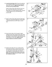
...66) at the second hole from the top of the Weight 45 Tube (47). Attach the Pulley and a Cable Trap (68) to the indicated bracket on top of the two Pulley Plates (51) with an M10 x... x 19mm Spacers (102), and an M10 Nylon Locknut (90). 75 99 102 99 90 63 110 5 42. Route the Weight Cable (110) over a 90mm Pulley (63). Set the M12 Washer (33) on the Right Top Frame (5) with an... Frame with an M10 x 48mm Bolt (64) and an M10 Nylon Locknut (90). Wrap the Weight Cable (110) over a 90mm 41 Pulley (63) and down through the Right Top Frame (5). Thread the M12 Nut...
...66) at the second hole from the top of the Weight 45 Tube (47). Attach the Pulley and a Cable Trap (68) to the indicated bracket on top of the two Pulley Plates (51) with an M10 x... x 19mm Spacers (102), and an M10 Nylon Locknut (90). 75 99 102 99 90 63 110 5 42. Route the Weight Cable (110) over a 90mm Pulley (63). Set the M12 Washer (33) on the Right Top Frame (5) with an... Frame with an M10 x 48mm Bolt (64) and an M10 Nylon Locknut (90). Wrap the Weight Cable (110) over a 90mm 41 Pulley (63) and down through the Right Top Frame (5). Thread the M12 Nut...
English Manual
Page 18
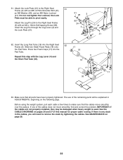
... Finger Guards (66) to the Right Base (1) with an M10 x 43mm Bolt (80) and an M10 Nylon Locknut (90). 90 63 3 107 80 48. Route the Ab Cable (107) through the Leg Lever (4) and the Right Seat Frame (3). Attach the Pulley and two Half Finger Guards (66) to the lower hole in.... 107 2 90 66 63 66 64 1 49. Locate the Ab Cable (107). Attach a 90mm Pulley (63) inside the Leg Lever (4), over the Ab Cable (107), with an M10 x 48mm Bolt (64) and an M10 Nylon Locknut (90). Route the small ball on the Cable through the Right 48 Upright (2) and under a 90mm Pulley (63...
... Finger Guards (66) to the Right Base (1) with an M10 x 43mm Bolt (80) and an M10 Nylon Locknut (90). 90 63 3 107 80 48. Route the Ab Cable (107) through the Leg Lever (4) and the Right Seat Frame (3). Attach the Pulley and two Half Finger Guards (66) to the lower hole in.... 107 2 90 66 63 66 64 1 49. Locate the Ab Cable (107). Attach a 90mm Pulley (63) inside the Leg Lever (4), over the Ab Cable (107), with an M10 x 48mm Bolt (64) and an M10 Nylon Locknut (90). Route the small ball on the Cable through the Right 48 Upright (2) and under a 90mm Pulley (63...
English Manual
Page 22
... on page 28. 22 Insert the Long Pad Tube (16) into the Pad Tube. 17 18 Repeat this manual for proper cable routing. If there is used. the Lock Plate must be explained in ADJUSTMENTS, beginning on the following page. Press two Foam Caps (17) into the Right ... step with an M8 x 67mm Shoulder Bolt (41), an M8 Washer (98), and an M8 Nylon Locknut (91). Before using the weight system, pull each cable a few times to the Right Seat 61 Frame (3) with the Leg Lever (4) and the Short Pad Tube (35). 3 16 4 35 18 17 63. Do not...
... on page 28. 22 Insert the Long Pad Tube (16) into the Pad Tube. 17 18 Repeat this manual for proper cable routing. If there is used. the Lock Plate must be explained in ADJUSTMENTS, beginning on the following page. Press two Foam Caps (17) into the Right ... step with an M8 x 67mm Shoulder Bolt (41), an M8 Washer (98), and an M8 Nylon Locknut (91). Before using the weight system, pull each cable a few times to the Right Seat 61 Frame (3) with the Leg Lever (4) and the Short Pad Tube (35). 3 16 4 35 18 17 63. Do not...
English Manual
Page 26
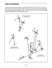
... the cables. If the cables have been assembled correctly. Butterfly Cable (106) 4 Length: 5 feet 2 5 1 3 2 1 3 Short Cable (108) Length: 3 feet 11 inches 2 1 6 10 4 8 5 3 7 9 Ab Cable (107) Length: 21 feet 1 inch 26 The numbers show the proper routing of the Butterfly Cable (106), the Ab Cable (107), the Short Cable (108), the Press Cable (109), and the Weight Cable (110). CABLE DIAGRAMS The cable diagrams...
... the cables. If the cables have been assembled correctly. Butterfly Cable (106) 4 Length: 5 feet 2 5 1 3 2 1 3 Short Cable (108) Length: 3 feet 11 inches 2 1 6 10 4 8 5 3 7 9 Ab Cable (107) Length: 21 feet 1 inch 26 The numbers show the proper routing of the Butterfly Cable (106), the Ab Cable (107), the Short Cable (108), the Press Cable (109), and the Weight Cable (110). CABLE DIAGRAMS The cable diagrams...


