
English Manual
Page 2
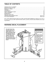
TABLE OF CONTENTS WARNING DECAL PLACEMENT 2 IMPORTANT PRECAUTIONS 3 BEFORE YOU BEGIN 4 ASSEMBLY 5 ADJUSTMENTS 23 WEIGHT RESISTANCE CHART 25 CABLE DIAGRAMS 26 MAINTENANCE 28 EXERCISE GUIDELINES 29 ORDERING REPLACEMENT PARTS Back Cover FULL 90-DAY WARRANTY Back Cover Note: A PART IDENTIFICATION CHART and a PART LIST/EXPLODED ...
TABLE OF CONTENTS WARNING DECAL PLACEMENT 2 IMPORTANT PRECAUTIONS 3 BEFORE YOU BEGIN 4 ASSEMBLY 5 ADJUSTMENTS 23 WEIGHT RESISTANCE CHART 25 CABLE DIAGRAMS 26 MAINTENANCE 28 EXERCISE GUIDELINES 29 ORDERING REPLACEMENT PARTS Back Cover FULL 90-DAY WARRANTY Back Cover Note: A PART IDENTIFICATION CHART and a PART LIST/EXPLODED ...
English Manual
Page 12
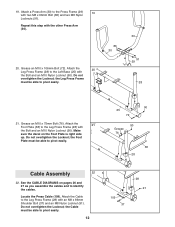
...) with two M8 x 66mm Bolt (86) and two M8 Nylon Locknuts (91). Make sure the decal on pages 26 and 27 as you assemble the cables and to pivot easily. 12 109 37 28 91 Do not overtighten the Locknut; Do not overtighten the Locknut; the Foot Plate must be able... Bolt and an M10 Nylon Locknut (90). Locate the Press Cable (109). the Cable must be able to identify the cables. Attach the 21 Foot Plate (38) to the Left Base (25) with the Bolt and an M10 Nylon Locknut (90). See the CABLE DIAGRAMS on the Foot Plate is right side up. Repeat this...
...) with two M8 x 66mm Bolt (86) and two M8 Nylon Locknuts (91). Make sure the decal on pages 26 and 27 as you assemble the cables and to pivot easily. 12 109 37 28 91 Do not overtighten the Locknut; Do not overtighten the Locknut; the Foot Plate must be able... Bolt and an M10 Nylon Locknut (90). Locate the Press Cable (109). the Cable must be able to identify the cables. Attach the 21 Foot Plate (38) to the Left Base (25) with the Bolt and an M10 Nylon Locknut (90). See the CABLE DIAGRAMS on the Foot Plate is right side up. Repeat this...
English Manual
Page 22
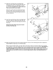
... Washer (98), and an M8 Nylon Locknut (91). If there is used. Press two Foam Caps (17) into the Right Seat 62 Frame (3). See the CABLE DIAGRAMS on the following page. See MAINTENANCE on page 28. 22 the Lock Plate must be damaged when heavy weight is any slack in the... Pad Tube. 61. Insert the Leg Pin through the Leg Lever (4) and the Lock Plate (21). 89 24 4 21 41 62. Make sure that the cables move smoothly, find and correct the problem. Attach the Lock Plate (21) to the Right Seat Frame (3) with the Leg Lever (4) and the Short Pad...
... Washer (98), and an M8 Nylon Locknut (91). If there is used. Press two Foam Caps (17) into the Right Seat 62 Frame (3). See the CABLE DIAGRAMS on the following page. See MAINTENANCE on page 28. 22 the Lock Plate must be damaged when heavy weight is any slack in the... Pad Tube. 61. Insert the Leg Pin through the Leg Lever (4) and the Lock Plate (21). 89 24 4 21 41 62. Make sure that the cables move smoothly, find and correct the problem. Attach the Lock Plate (21) to the Right Seat Frame (3) with the Leg Lever (4) and the Short Pad...
English Manual
Page 26
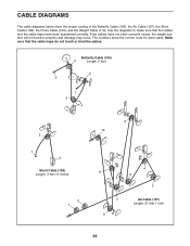
... the proper routing of the Butterfly Cable (106), the Ab Cable (107), the Short Cable (108), the Press Cable (109), and the Weight Cable (110). Make sure that the cables and the cable traps have not been correctly routed, the weight system will not function properly and damage may occur. CABLE DIAGRAMS The cable diagrams below show the correct route for...
... the proper routing of the Butterfly Cable (106), the Ab Cable (107), the Short Cable (108), the Press Cable (109), and the Weight Cable (110). Make sure that the cables and the cable traps have not been correctly routed, the weight system will not function properly and damage may occur. CABLE DIAGRAMS The cable diagrams below show the correct route for...


