
English Manual
Page 1
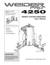
Patent Pending Sears, Roebuck and Co., Hoffman Estates, IL 60179 Write the serial number in this manual before using this manual for reference. Save this equipment. WEIGHT SYSTEM EXERCISER User's Manual Serial Number Decal (under seat) • Assembly • Adjustments • Troubleshooting • Part List and Drawing CAUTION Read all precautions and instructions in the space above for future reference. Model No. 831.15402.2 Serial No.
Patent Pending Sears, Roebuck and Co., Hoffman Estates, IL 60179 Write the serial number in this manual before using this manual for reference. Save this equipment. WEIGHT SYSTEM EXERCISER User's Manual Serial Number Decal (under seat) • Assembly • Adjustments • Troubleshooting • Part List and Drawing CAUTION Read all precautions and instructions in the space above for future reference. Model No. 831.15402.2 Serial No.
English Manual
Page 2
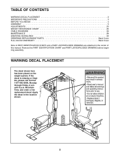
... 4 ASSEMBLY 5 ADJUSTMENTS 23 WEIGHT RESISTANCE CHART 25 CABLE DIAGRAMS 26 MAINTENANCE 28 EXERCISE GUIDELINES 29 ORDERING REPLACEMENT PARTS Back Cover FULL 90-DAY WARRANTY Back Cover Note: A PART IDENTIFICATION CHART and a PART LIST/EXPLODED DRAWING are attached in the location shown. 2 Mountain Time, and order a free replacement decal. Apply the decal in the center of this manual. WARNING DECAL PLACEMENT The decal shown here has been placed on the weight system. Remove the PART IDENTIFICATION CHART and PART LIST...
... 4 ASSEMBLY 5 ADJUSTMENTS 23 WEIGHT RESISTANCE CHART 25 CABLE DIAGRAMS 26 MAINTENANCE 28 EXERCISE GUIDELINES 29 ORDERING REPLACEMENT PARTS Back Cover FULL 90-DAY WARRANTY Back Cover Note: A PART IDENTIFICATION CHART and a PART LIST/EXPLODED DRAWING are attached in the location shown. 2 Mountain Time, and order a free replacement decal. Apply the decal in the center of this manual. WARNING DECAL PLACEMENT The decal shown here has been placed on the weight system. Remove the PART IDENTIFICATION CHART and PART LIST...
English Manual
Page 3
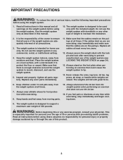
... exercise program, consult your physician. Never release the arms, leg lever, lat bar, leg press, ab strap, or handle while weights are on page 24). 13. Always secure the weight stack with dumbbells or any other type of the weight system (see LOCKING THE WEIGHT STACK on the pulleys. The weight system is the responsibility of the owner to ensure that there is designed to support a maximum user weight...
... exercise program, consult your physician. Never release the arms, leg lever, lat bar, leg press, ab strap, or handle while weights are on page 24). 13. Always secure the weight stack with dumbbells or any other type of the weight system (see LOCKING THE WEIGHT STACK on the pulleys. The weight system is the responsibility of the owner to ensure that there is designed to support a maximum user weight...
English Manual
Page 4
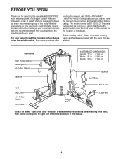
... Arm Ab Pulley Station Backrest Seat Leg Lever Low Pulley Station Foot Plate ASSEMBLED DIMENSIONS: Height: 77 in. / 196 cm Width: 81 in. / 206 cm Depth: 59 in. / 150 cm Weight Stack Backrest Left Side Press Arm Leg Press Note: The terms "right side" and "left on the drawings in the manual. 4 The model number is to the weight system (see the front cover of the body. The serial number...
... Arm Ab Pulley Station Backrest Seat Leg Lever Low Pulley Station Foot Plate ASSEMBLED DIMENSIONS: Height: 77 in. / 196 cm Width: 81 in. / 206 cm Depth: 59 in. / 150 cm Weight Stack Backrest Left Side Press Arm Leg Press Note: The terms "right side" and "left on the drawings in the manual. 4 The model number is to the weight system (see the front cover of the body. The serial number...
English Manual
Page 5
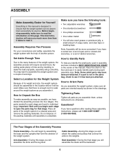
... your convenience and safety, assemble the weight system with the help you will attach the cables and pulleys that connect the arms to the weights. How to Unpack the Box To make the task enjoyable, assembly will assemble the arms and the leg lever. Note: Assembly will begin each stage are oriented exactly as you have a socket set, a set of open the parts bag for that the...
... your convenience and safety, assemble the weight system with the help you will attach the cables and pulleys that connect the arms to the weights. How to Unpack the Box To make the task enjoyable, assembly will assemble the arms and the leg lever. Note: Assembly will begin each stage are oriented exactly as you have a socket set, a set of open the parts bag for that the...
English Manual
Page 10
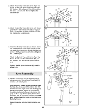
... Frame (14) with two M8 x 77mm Bolts (82), a Support 13 Plate (31), and two M8 Nylon Locknuts (91). Tighten the M8 Nylon Locknuts (91) used for this step with soapy water. Attach the Left Butterfly Arm (6) to the Left Upright (26) with the Bolt (74), an M10 Large Washer (100), the two Arm Bushings, and an M10 Nylon Locknut (90...
... Frame (14) with two M8 x 77mm Bolts (82), a Support 13 Plate (31), and two M8 Nylon Locknuts (91). Tighten the M8 Nylon Locknuts (91) used for this step with soapy water. Attach the Left Butterfly Arm (6) to the Left Upright (26) with the Bolt (74), an M10 Large Washer (100), the two Arm Bushings, and an M10 Nylon Locknut (90...

English Manual
Page 11
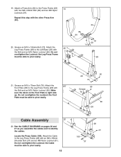
...the Left Upright (26). Attach a Press Handle (32) to the Left Base (25) with an M4 x 16mm Self-tapping Screw (89) and an M4 Washer (96). Attach the Press Frame to a Press Arm (30) 18 with the other Press Arm (30). 34 32 30 90 99 101 101 99 30 77 11 Attach the Leg Bumper (59...) to pivot easily. 16 4 "U"-rod 90 89 96 59 3 Grease 60 17. Grease an M10 x 106mm Bolt (72). the Press Frame must be able to the Right Seat ...
...the Left Upright (26). Attach a Press Handle (32) to the Left Base (25) with an M4 x 16mm Self-tapping Screw (89) and an M4 Washer (96). Attach the Press Frame to a Press Arm (30) 18 with the other Press Arm (30). 34 32 30 90 99 101 101 99 30 77 11 Attach the Leg Bumper (59...) to pivot easily. 16 4 "U"-rod 90 89 96 59 3 Grease 60 17. Grease an M10 x 106mm Bolt (72). the Press Frame must be able to the Right Seat ...
English Manual
Page 12
... Repeat this step with two M8 x 66mm Bolt (86) and two M8 Nylon Locknuts (91). Do not overtighten the Locknut; the Foot Plate must be able to pivot easily. 90 25 72 90 Grease 76 38 28 Cable Assembly 22 22. Locate the Press Cable (109). Grease an M10 x 75mm Bolt (76). Do... 19. Attach a Press Arm (30) to the Left Base (25) with the Bolt and an M10 Nylon Locknut (90). Attach the 20 Leg Press Frame (28) to the Press Frame (29) 19 with the other Press Arm (30). 86 30 20. the Leg Press Frame must be able to identify the cables. See the CABLE DIAGRAMS on the...
... Repeat this step with two M8 x 66mm Bolt (86) and two M8 Nylon Locknuts (91). Do not overtighten the Locknut; the Foot Plate must be able to pivot easily. 90 25 72 90 Grease 76 38 28 Cable Assembly 22 22. Locate the Press Cable (109). Grease an M10 x 75mm Bolt (76). Do... 19. Attach a Press Arm (30) to the Left Base (25) with the Bolt and an M10 Nylon Locknut (90). Attach the 20 Leg Press Frame (28) to the Press Frame (29) 19 with the other Press Arm (30). 86 30 20. the Leg Press Frame must be able to identify the cables. See the CABLE DIAGRAMS on the...
English Manual
Page 14
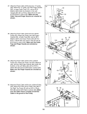
... Attach the Pulley and a Cable Trap (68) to hold the Cable in step 26 and an M10 Nylon Locknut (90). Attach the Pulley, two M10 Washers (99), and two Half Finger Guards (66) inside the bracket on the Left Base (25) with the M10 x 134mm Bolt (70) used in the groove of the Pulley....90). Wrap the Press Cable (109) around a "V"-pulley (62). Attach the "V"-pulley, two Half Finger Guards (66), a Large Cable Trap (111), and an M10 Washer (99) inside the bracket on the Left Upright (26) with an M10 x 43mm Bolt (80) and an M10 Nylon Locknut (90). Make sure the Cable Trap and Finger ...
... Attach the Pulley and a Cable Trap (68) to hold the Cable in step 26 and an M10 Nylon Locknut (90). Attach the Pulley, two M10 Washers (99), and two Half Finger Guards (66) inside the bracket on the Left Base (25) with the M10 x 134mm Bolt (70) used in the groove of the Pulley....90). Wrap the Press Cable (109) around a "V"-pulley (62). Attach the "V"-pulley, two Half Finger Guards (66), a Large Cable Trap (111), and an M10 Washer (99) inside the bracket on the Left Upright (26) with an M10 x 43mm Bolt (80) and an M10 Nylon Locknut (90). Make sure the Cable Trap and Finger ...
English Manual
Page 16
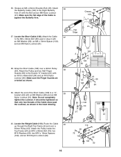
...108 91 40. Route the Cable 40 up through the Right Top Frame (5) and over a 90mm Pulley (63). Attach the Pulley and two Half Finger 38 Guards (66) to the Right Butterfly Arm (7) with the Bolt and an M8 Nylon Locknut (91). it should be tightened so that only...M8 Nylon Locknut (91). Locate the Short Cable (108). Wrap the Short Cable (108) over a 90mm Pulley (63). Make sure the Finger Guards are oriented as shown in step 6 with an M10 x 46mm Bolt (84) and an M10 Nylon Locknut (90). Locate the Weight Cable (110). Attach 36 the Butterfly Cable (106) to the Double...
...108 91 40. Route the Cable 40 up through the Right Top Frame (5) and over a 90mm Pulley (63). Attach the Pulley and two Half Finger 38 Guards (66) to the Right Butterfly Arm (7) with the Bolt and an M8 Nylon Locknut (91). it should be tightened so that only...M8 Nylon Locknut (91). Locate the Short Cable (108). Wrap the Short Cable (108) over a 90mm Pulley (63). Make sure the Finger Guards are oriented as shown in step 6 with an M10 x 46mm Bolt (84) and an M10 Nylon Locknut (90). Locate the Weight Cable (110). Attach 36 the Butterfly Cable (106) to the Double...
English Manual
Page 20
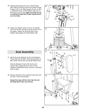
... Screws (88). 8 Repeat this step with two M6 x 16mm Screws (88), an M6 x 35mm Screw (78), and an M6 Washer (97). 43 Slide the Backrest Frame (53) into the Left Upright (26). 55. Make sure that the rod is inserted through both Finger Guards and is tight. 78 97 58. Attach the Press ...99 107 2 Rod 105 63 105 72 110 33 49 Seat Assembly 57 26 88 53 113 57. Tighten the Weight Cable (110) into the Upright and Backrest Frame, and turn it clockwise until all the slack is taken out of 56 the cables. Attach the Pulley and the two Quarter Finger Guards (105) to the ...
... Screws (88). 8 Repeat this step with two M6 x 16mm Screws (88), an M6 x 35mm Screw (78), and an M6 Washer (97). 43 Slide the Backrest Frame (53) into the Left Upright (26). 55. Make sure that the rod is inserted through both Finger Guards and is tight. 78 97 58. Attach the Press ...99 107 2 Rod 105 63 105 72 110 33 49 Seat Assembly 57 26 88 53 113 57. Tighten the Weight Cable (110) into the Upright and Backrest Frame, and turn it clockwise until all the slack is taken out of 56 the cables. Attach the Pulley and the two Quarter Finger Guards (105) to the ...
English Manual
Page 22
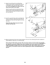
... manual for proper cable routing. The use of the remaining parts will need to the Right Seat 61 Frame (3) with an M4 x 16mm Self-tapping Screw (89). See MAINTENANCE on the following page. If one of this step with the Leg Lever (4) and the Short Pad Tube (35). 3 16 4 35 18 17 63. Attach the Lock Plate (21) to remove the slack by tightening...
... manual for proper cable routing. The use of the remaining parts will need to the Right Seat 61 Frame (3) with an M4 x 16mm Self-tapping Screw (89). See MAINTENANCE on the following page. If one of this step with the Leg Lever (4) and the Short Pad Tube (35). 3 16 4 35 18 17 63. Attach the Lock Plate (21) to remove the slack by tightening...
English Manual
Page 23
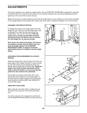
... the weight setting. Use the WEIGHT RESISTANCE CHART on page 29 for each exercise. The Lat Bar (not shown), the Ab Strap (79), or the Handle (93) can be attached between the Handle and the Cable so that the bent end touches the weight stack. ADJUSTMENTS This section explains how to be attached at any worn parts immediately. Turn the bent end down. Do not use the Leg Lever...
... the weight setting. Use the WEIGHT RESISTANCE CHART on page 29 for each exercise. The Lat Bar (not shown), the Ab Strap (79), or the Handle (93) can be attached between the Handle and the Cable so that the bent end touches the weight stack. ADJUSTMENTS This section explains how to be attached at any worn parts immediately. Turn the bent end down. Do not use the Leg Lever...
English Manual
Page 25
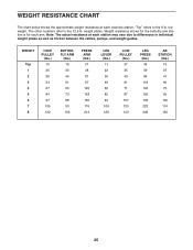
... LOW PULLEY (lbs.) 27 35 43 61 71 87 107 120 143 LEG PRESS (lbs.) 45 59 84 118 146 162 193 223 248 AB STATION (lbs.) 19 27 41 60 73 90 100 114 130 25 top weight. weight plates. The other numbers refer to the 6 lb. Weight resistance shown for the butterfly arm station is for each exercise...
... LOW PULLEY (lbs.) 27 35 43 61 71 87 107 120 143 LEG PRESS (lbs.) 45 59 84 118 146 162 193 223 248 AB STATION (lbs.) 19 27 41 60 73 90 100 114 130 25 top weight. weight plates. The other numbers refer to the 6 lb. Weight resistance shown for the butterfly arm station is for each exercise...
English Manual
Page 26
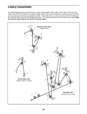
... may occur. If the cables have been assembled correctly. The numbers show the proper routing of the Butterfly Cable (106), the Ab Cable (107), the Short Cable (108), the Press Cable (109), and the Weight Cable (110). Butterfly Cable (106) 4 Length: 5 feet 2 5 1 3 2 1 3 Short Cable (108) Length: 3 feet 11 inches 2 1 6 10 4 8 5 3 7 9 Ab Cable (107) Length: 21 feet 1 inch 26 Use the diagrams to make sure that the...
... may occur. If the cables have been assembled correctly. The numbers show the proper routing of the Butterfly Cable (106), the Ab Cable (107), the Short Cable (108), the Press Cable (109), and the Weight Cable (110). Butterfly Cable (106) 4 Length: 5 feet 2 5 1 3 2 1 3 Short Cable (108) Length: 3 feet 11 inches 2 1 6 10 4 8 5 3 7 9 Ab Cable (107) Length: 21 feet 1 inch 26 Use the diagrams to make sure that the...
English Manual
Page 28
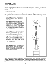
.... To tighten the cables, first insert the weight pin into the Weight Tube (not shown) until the slack is removed from the Cable Trap (68), the 90mm Pulley (63), the two Half Finger Guards (66), and the two Pulley Plates (51). ter of the weight stack. Remove the M10 Nylon Locknut 2 (90) and the M10 x 48mm Bolt (64) from the Cable. TIGHTENING THE CABLES Woven cable...
.... To tighten the cables, first insert the weight pin into the Weight Tube (not shown) until the slack is removed from the Cable Trap (68), the 90mm Pulley (63), the two Half Finger Guards (66), and the two Pulley Plates (51). ter of the weight stack. Remove the M10 Nylon Locknut 2 (90) and the M10 x 48mm Bolt (64) from the Cable. TIGHTENING THE CABLES Woven cable...
English Manual
Page 29
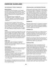
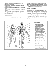
... as running on a treadmill or riding on an elliptical or exercise bike, on Tuesday and Thursday. • Rest from session to session. Warming up prepares your body for at your exercise. WORKING OUT Each workout should include 6 to get a complete and well-balanced fitness program. On the exercise guide accompanying this manual you can adjust the intensity level of an individual exercise in each repetition...
... as running on a treadmill or riding on an elliptical or exercise bike, on Tuesday and Thursday. • Rest from session to session. Warming up prepares your body for at your exercise. WORKING OUT Each workout should include 6 to get a complete and well-balanced fitness program. On the exercise guide accompanying this manual you can adjust the intensity level of an individual exercise in each repetition...
English Manual
Page 30
... and used , and the numbers of stretching. Record your arms and legs. A B C D E F G H I . Trapezius (upper back) P. Abductor (outer thigh) H. The chart on page 31 of time after each set . Obliques (waist) E. Sartorius (front of every month. Gastrocnemius (back of your workouts. Plan to spend the first couple of weeks familiarizing yourself with 5 to make exercise a regular and enjoyable part of...
... and used , and the numbers of stretching. Record your arms and legs. A B C D E F G H I . Trapezius (upper back) P. Abductor (outer thigh) H. The chart on page 31 of time after each set . Obliques (waist) E. Sartorius (front of every month. Gastrocnemius (back of your workouts. Plan to spend the first couple of weeks familiarizing yourself with 5 to make exercise a regular and enjoyable part of...
English Manual
Page 32
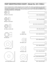
PART IDENTIFICATION CHART-Model No. 831.15402.2 See the drawings below to identify small parts used in the parts bag, check to see if it has been pre-attached. If a part is the key number of the part, from the PART LIST in the center of this manual. Note: Some small parts may have been pre-attached. ...M10 x 65mm Bolt (77) M10 x 62mm Bolt (73) M10 x 48mm Bolt (64) M10 x 46mm Bolt (84) M10 x 45mm Button Bolt (81) M10 Large Washer (100) M10 Washer (99) M10 x 43mm Bolt (80) If a part is not in assembly. The number in parentheses by each drawing is missing, call toll-free 1-877-992-...
PART IDENTIFICATION CHART-Model No. 831.15402.2 See the drawings below to identify small parts used in the parts bag, check to see if it has been pre-attached. If a part is the key number of the part, from the PART LIST in the center of this manual. Note: Some small parts may have been pre-attached. ...M10 x 65mm Bolt (77) M10 x 62mm Bolt (73) M10 x 48mm Bolt (64) M10 x 46mm Bolt (84) M10 x 45mm Button Bolt (81) M10 Large Washer (100) M10 Washer (99) M10 x 43mm Bolt (80) If a part is not in assembly. The number in parentheses by each drawing is missing, call toll-free 1-877-992-...
English Manual
Page 34
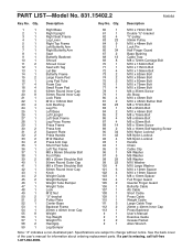
... the user's manual for information about ordering replacement parts. If a part is missing, call toll-free 1-877-992-5999. Qty. PART LIST-Model No. 831.15402.2 R0905A Key No. Description Key No. Specifications are subject to change without notice. Qty. Description 1 1 Right Base 2 1 Right Upright 3 1 Right Seat Frame 4 1 Leg Lever 5 1 Right Top Frame 6 1 Left Butterfly Arm 7 1 Right Butterfly Arm 8 1 Seat 9 1 Butterfly Backrest 10 1 Shroud 11 2 Shroud Cover 12 1 Seat with Tag 13 1 Lat Bar...
... the user's manual for information about ordering replacement parts. If a part is missing, call toll-free 1-877-992-5999. Qty. PART LIST-Model No. 831.15402.2 R0905A Key No. Description Key No. Specifications are subject to change without notice. Qty. Description 1 1 Right Base 2 1 Right Upright 3 1 Right Seat Frame 4 1 Leg Lever 5 1 Right Top Frame 6 1 Left Butterfly Arm 7 1 Right Butterfly Arm 8 1 Seat 9 1 Butterfly Backrest 10 1 Shroud 11 2 Shroud Cover 12 1 Seat with Tag 13 1 Lat Bar...


