
English Manual
Page 1
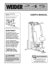
... CAUTION Read all precautions and instructions in the space above for future reference. Write the serial number in this manual before using this manual for reference. Visit our website at www.weiderfitness.com new products, prizes, fitness tips, and much more! USER'S MANUAL Serial Number Decal (under seat) QUESTIONS? TO AVOID UNNECESSARY DELAYS, PLEASE CALL DIRECT TO OUR TOLL-FREE CUSTOMER HOT LINE. Save this...
... CAUTION Read all precautions and instructions in the space above for future reference. Write the serial number in this manual before using this manual for reference. Visit our website at www.weiderfitness.com new products, prizes, fitness tips, and much more! USER'S MANUAL Serial Number Decal (under seat) QUESTIONS? TO AVOID UNNECESSARY DELAYS, PLEASE CALL DIRECT TO OUR TOLL-FREE CUSTOMER HOT LINE. Save this...
English Manual
Page 2
TABLE OF CONTENTS IMPORTANT PRECAUTIONS 3 BEFORE YOU BEGIN 4 PART IDENTIFICATION CHART 5 ASSEMBLY 7 ADJUSTMENT 18 WEIGHT RESISTANCE CHART 19 TROUBLE-SHOOTING AND MAINTENANCE 20 CABLE DIAGRAM 21 PART LIST 22 EXPLODED DRAWING 23 ORDERING REPLACEMENT PARTS Back Cover LIMITED WARRANTY Back Cover WEIDER is a registered trademark of ICON Health & Fitness, Inc. 2
TABLE OF CONTENTS IMPORTANT PRECAUTIONS 3 BEFORE YOU BEGIN 4 PART IDENTIFICATION CHART 5 ASSEMBLY 7 ADJUSTMENT 18 WEIGHT RESISTANCE CHART 19 TROUBLE-SHOOTING AND MAINTENANCE 20 CABLE DIAGRAM 21 PART LIST 22 EXPLODED DRAWING 23 ORDERING REPLACEMENT PARTS Back Cover LIMITED WARRANTY Back Cover WEIDER is a registered trademark of ICON Health & Fitness, Inc. 2
English Manual
Page 3
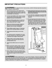
... use the lat bar. 13. Never release the press arm, butterfly arms, leg lever, lat bar, or nylon strap while weights are exercising, stop immediately and begin cooling down. 14. Replace any time while exercising, stop immediately and make sure that could cause the training system to protect the floor or carpet. 4. Apply the decal in the indicated location. The training system is missing or illegible, call our toll-free...
... use the lat bar. 13. Never release the press arm, butterfly arms, leg lever, lat bar, or nylon strap while weights are exercising, stop immediately and begin cooling down. 14. Replace any time while exercising, stop immediately and make sure that could cause the training system to protect the floor or carpet. 4. Apply the decal in the indicated location. The training system is missing or illegible, call our toll-free...
English Manual
Page 4
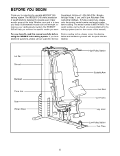
...; 245 training system. until 6 p.m. The serial number can be found on a decal attached to develop every major muscle group of this manual carefully before calling. BEFORE YOU BEGIN Thank you have below and familiarize yourself with the parts that are additional questions, please call our Customer Service labeled. Lat Bar Shroud Backrest Press Arm Seat Weight Stack High Pulley Station Butterfly Arm Curl Pad Curl Frame Leg...
...; 245 training system. until 6 p.m. The serial number can be found on a decal attached to develop every major muscle group of this manual carefully before calling. BEFORE YOU BEGIN Thank you have below and familiarize yourself with the parts that are additional questions, please call our Customer Service labeled. Lat Bar Shroud Backrest Press Arm Seat Weight Stack High Pulley Station Butterfly Arm Curl Pad Curl Frame Leg...
English Manual
Page 5
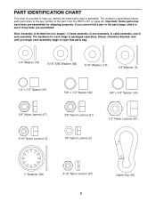
.... Unless otherwise directed, wait until you begin each part refers to the key number of the part, from the PART LIST on page 22. PART IDENTIFICATION CHART This chart is provided to help you cannot find a part in the parts bags, check to see if it has been pre-assembled. If you identify the small parts used in parenthesis below each assembly stage to open that parts bag...
.... Unless otherwise directed, wait until you begin each part refers to the key number of the part, from the PART LIST on page 22. PART IDENTIFICATION CHART This chart is provided to help you cannot find a part in the parts bags, check to see if it has been pre-assembled. If you identify the small parts used in parenthesis below each assembly stage to open that parts bag...
English Manual
Page 7
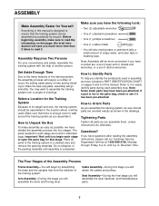
... it takes to assemble the training system over a couple of ratchet wrenches. Mountain Time. Cable Assembly-During this manual is not in assembly, we have a socket set, a set of the packing materials until 6 p.m. Seat Assembly-During the final stage you assemble them, unless instructed to it has been pre-attached. Before beginning assembly, make assembly as easy as you will assemble the arms and the leg lever. Make...
... it takes to assemble the training system over a couple of ratchet wrenches. Mountain Time. Cable Assembly-During this manual is not in assembly, we have a socket set, a set of the packing materials until 6 p.m. Seat Assembly-During the final stage you assemble them, unless instructed to it has been pre-attached. Before beginning assembly, make assembly as easy as you will assemble the arms and the leg lever. Make...
English Manual
Page 10
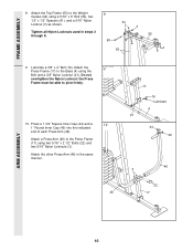
... of each Press Arm (46). Attach the other Press Arm (46) in steps 3 through 8. 8 60 61 3 55 62 9. Lubricate a 3/8" x 4" Bolt (16). Attach a Press Arm (46) to the Weight Guides (62) using a 5/16" x 6" Bolt (60), two 1/2" x 1/2" Spacers (61), and a 5/16" Nylon Locknut (3) as shown. FRAME ASSEMBLY 8. Do not overtighten the Nylon Locknut; Attach the Top Frame (55) to the Press Frame (17) using the Bolt and a 3/8" Nylon Locknut (21). Tighten all Nylon...
... of each Press Arm (46). Attach the other Press Arm (46) in steps 3 through 8. 8 60 61 3 55 62 9. Lubricate a 3/8" x 4" Bolt (16). Attach a Press Arm (46) to the Weight Guides (62) using a 5/16" x 6" Bolt (60), two 1/2" x 1/2" Spacers (61), and a 5/16" Nylon Locknut (3) as shown. FRAME ASSEMBLY 8. Do not overtighten the Nylon Locknut; Attach the Top Frame (55) to the Press Frame (17) using the Bolt and a 3/8" Nylon Locknut (21). Tighten all Nylon...
English Manual
Page 11
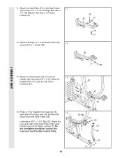
... Leg Lever (29) to pivot freely. 36 32 3 36 22 32 29 32 11 Attach the Seat Frame (36) to the Seat Frame 11 (36) using the Bolt and a 5/16" Nylon Locknut (3). Attach the Seat Plate (37) to the Front 13 Upright (42) using a #10 x 1" Screw (80). 78 2 36 11 80 ARM ASSEMBLY 13. 11. Attach a Bumper (11) to the Seat Frame (36) 12 using two 3/8" x 3 1/4" Bolts...
... Leg Lever (29) to pivot freely. 36 32 3 36 22 32 29 32 11 Attach the Seat Frame (36) to the Seat Frame 11 (36) using the Bolt and a 5/16" Nylon Locknut (3). Attach the Seat Plate (37) to the Front 13 Upright (42) using a #10 x 1" Screw (80). 78 2 36 11 80 ARM ASSEMBLY 13. 11. Attach a Bumper (11) to the Seat Frame (36) 12 using two 3/8" x 3 1/4" Bolts...
English Manual
Page 12
...) onto the Left Arm. Attach the Left Arm (47) in steps 17-30, refer to turn freely. 16 55 Lubricate Axle 47 Bracket 68 65 68 48 65 17 23 8 6 55 9 82 21 9 82 Ball 18 50 76 55 6 23 67 CABLE ASSEMBLY 12 Important: As you assemble the cables in the same manner. 17. the Pulley must be able to...
...) onto the Left Arm. Attach the Left Arm (47) in steps 17-30, refer to turn freely. 16 55 Lubricate Axle 47 Bracket 68 65 68 48 65 17 23 8 6 55 9 82 21 9 82 Ball 18 50 76 55 6 23 67 CABLE ASSEMBLY 12 Important: As you assemble the cables in the same manner. 17. the Pulley must be able to...
English Manual
Page 13
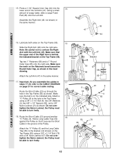
... the Pulley Bracket as shown. CABLE ASSEMBLY 19. Route the Short Cable (23) around two "V"- 19 Pulleys (6). Remove the 4 1/2" Pulley (74). Attach the Pulleys and two Long Cable Traps (50) to the Weight Tube (63) using a 5/16" x 1 3/4" Bolt (86) and a 5/16" Nylon Locknut (3). 21 23 74 40 9 8 40 9 21 55 Loop 22 23 57 78 86 3 2 63 13 Open the bag marked "Pro-Pulley". Attach the Pulley using two 3/8" x 6 2 1/2" Bolts (7) and...
... the Pulley Bracket as shown. CABLE ASSEMBLY 19. Route the Short Cable (23) around two "V"- 19 Pulleys (6). Remove the 4 1/2" Pulley (74). Attach the Pulleys and two Long Cable Traps (50) to the Weight Tube (63) using a 5/16" x 1 3/4" Bolt (86) and a 5/16" Nylon Locknut (3). 21 23 74 40 9 8 40 9 21 55 Loop 22 23 57 78 86 3 2 63 13 Open the bag marked "Pro-Pulley". Attach the Pulley using two 3/8" x 6 2 1/2" Bolts (7) and...
English Manual
Page 14
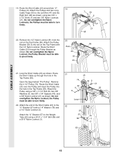
... pre-assembled 3 1/2" Pulleys (15) from the Pulley Plates (58). Do not tighten the Nylon Locknut yet. Hold a Cable Trap (66) against a 3 1/2" Pulley (15). Attach the 3 1/2" Pulley (15) and the Cable Trap (66) to turn freely. 24. CABLE ASSEMBLY 23. Reattach a Pulley Plate to the bottom set of holes in the groove. Route the Long Cable (69) around a 3 1/2" Pulley (15) as shown. Attach the Pulley to each side of the Pulleys. Locate...
... pre-assembled 3 1/2" Pulleys (15) from the Pulley Plates (58). Do not tighten the Nylon Locknut yet. Hold a Cable Trap (66) against a 3 1/2" Pulley (15). Attach the 3 1/2" Pulley (15) and the Cable Trap (66) to turn freely. 24. CABLE ASSEMBLY 23. Reattach a Pulley Plate to the bottom set of holes in the groove. Route the Long Cable (69) around a 3 1/2" Pulley (15) as shown. Attach the Pulley to each side of the Pulleys. Locate...
English Manual
Page 15
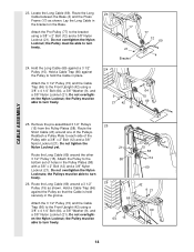
... 15 Do not overtighten the Nylon Locknut; Route the Long Cable (69) behind the Press Frame (17) and under the Seat Frame (36) as shown. Attach the 3 1/2" Pulley (15) and the Cable Trap (66) to hold the Long Cable in step 27. Hold a Long Cable Trap (50) against the Pulley to the Front Upright (42) using a 3/8" x 4 1/4" Bolt (64), a 3/8" Washer (9), and a 3/8" Nylon Locknut (21). Do...
... 15 Do not overtighten the Nylon Locknut; Route the Long Cable (69) behind the Press Frame (17) and under the Seat Frame (36) as shown. Attach the 3 1/2" Pulley (15) and the Cable Trap (66) to hold the Long Cable in step 27. Hold a Long Cable Trap (50) against the Pulley to the Front Upright (42) using a 3/8" x 4 1/4" Bolt (64), a 3/8" Washer (9), and a 3/8" Nylon Locknut (21). Do...
English Manual
Page 16
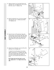
... use, replace the 1 1/2" Square Inner Cap (32). 36 16 Attach the Curl Pad (24) to the Curl Post (35) with two 1/4" x 3/4" Bolts (18). 34 24 To attach the Curl Post (35) to the Front Upright (42) using two 1/4" x 3/4" Bolts (18), a 1/4" x 2 1/4" Bolt (33), and a 1/4" Washer (78). 13 32. Insert the Curl Post into the Seat Frame and tighten the Knob (51) into the Seat...
... use, replace the 1 1/2" Square Inner Cap (32). 36 16 Attach the Curl Pad (24) to the Curl Post (35) with two 1/4" x 3/4" Bolts (18). 34 24 To attach the Curl Post (35) to the Front Upright (42) using two 1/4" x 3/4" Bolts (18), a 1/4" x 2 1/4" Bolt (33), and a 1/4" Washer (78). 13 32. Insert the Curl Post into the Seat Frame and tighten the Knob (51) into the Seat...
English Manual
Page 17
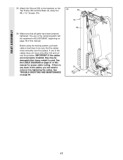
... proper cable routing. IMPORTANT: If the cables are not properly installed, they may be sure that all parts have been properly tightened. See the CABLE DIAGRAM on page 20. 59 79 4 17 The use of the remaining parts will need to the brackets on page 18 of the cables does not move smoothly over the pulleys. SEAT ASSEMBLY 35. Attach the Shroud (59) to remove it by tightening the cables.
... proper cable routing. IMPORTANT: If the cables are not properly installed, they may be sure that all parts have been properly tightened. See the CABLE DIAGRAM on page 20. 59 79 4 17 The use of the remaining parts will need to the brackets on page 18 of the cables does not move smoothly over the pulleys. SEAT ASSEMBLY 35. Attach the Shroud (59) to remove it by tightening the cables.
English Manual
Page 18
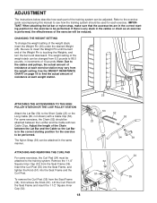
... exercise to the training system. ATTACHING AND REMOVING THE CURL PAD For some exercises, the Chain (52) should be performed. The Nylon Strap (39) can be reduced. ADJUSTMENT The instructions below describe how each weight station. Refer to the exercise guide accompanying this manual to see how the training system should be performed. Be sure to be attached between the Lat Bar and the Cable so the Lat Bar...
... exercise to the training system. ATTACHING AND REMOVING THE CURL PAD For some exercises, the Chain (52) should be performed. The Nylon Strap (39) can be reduced. ADJUSTMENT The instructions below describe how each weight station. Refer to the exercise guide accompanying this manual to see how the training system should be performed. Be sure to be attached between the Lat Bar and the Cable so the Lat Bar...
English Manual
Page 19
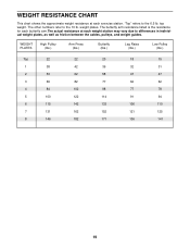
top weight. WEIGHT RESISTANCE CHART This chart shows the approximate weight resistance at each exercise station. The butterfly arm resistance listed is the resistance for each butterfly arm.The actual resistance at each weight station may vary due to differences in individual weight plates, as well as friction between the cables, pulleys, and weight guides. weight plates. WEIGHT PLATES High Pulley (lbs.) Arm Press (lbs.) Butterfly (lbs.) Leg Raise (lbs.) Low Pulley (lbs.) Top 22 22 20 18...
top weight. WEIGHT RESISTANCE CHART This chart shows the approximate weight resistance at each exercise station. The butterfly arm resistance listed is the resistance for each butterfly arm.The actual resistance at each weight station may vary due to differences in individual weight plates, as well as friction between the cables, pulleys, and weight guides. weight plates. WEIGHT PLATES High Pulley (lbs.) Arm Press (lbs.) Butterfly (lbs.) Leg Raise (lbs.) Low Pulley (lbs.) Top 22 22 20 18...
English Manual
Page 20
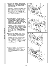
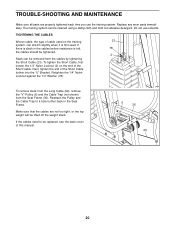
... manual. 6 36 69 20 Reattach the Pulley and the Cable Trap to be replaced, see the back cover of the Short Cable. If the cables need to a hole further back in the cables before resistance is felt, 78 the cables should be tightened. 2 Slack can be removed from the Seat Frame (36). Do not use the training system. Replace any worn parts immediately. If there is first used. To tighten...
... manual. 6 36 69 20 Reattach the Pulley and the Cable Trap to be replaced, see the back cover of the Short Cable. If the cables need to a hole further back in the cables before resistance is felt, 78 the cables should be tightened. 2 Slack can be removed from the Seat Frame (36). Do not use the training system. Replace any worn parts immediately. If there is first used. To tighten...
English Manual
Page 21
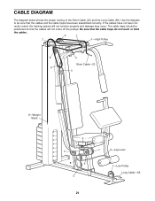
... not been cor- Use the diagram to be positioned so that the cable traps do not touch or bind the cables. 2 3 7 1-High Pulley 5 4 Short Cable-23 6 3 8-Weight Stack 6 4 8 5 2 7 9-Leg Lever 1-Low Pulley Long Cable-69 21 Be sure that the cables will not function properly and damage may occur. rectly routed, the training system will not come off the pulleys. CABLE DIAGRAM The diagram below shows the...
... not been cor- Use the diagram to be positioned so that the cable traps do not touch or bind the cables. 2 3 7 1-High Pulley 5 4 Short Cable-23 6 3 8-Weight Stack 6 4 8 5 2 7 9-Leg Lever 1-Low Pulley Long Cable-69 21 Be sure that the cables will not function properly and damage may occur. rectly routed, the training system will not come off the pulleys. CABLE DIAGRAM The diagram below shows the...
English Manual
Page 22
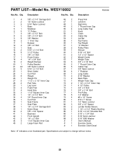
... Bolt 1/2" x 1/2" Spacer Weight Guide Weight Tube 3/8" x 4 1/4" Bolt 1" Round Outer Cap Cable Trap 3/8" Nylon Jamnut 1" Retainer Long Cable 5/16" Washer Back Plate Weight Tube Cap 1 1/2" x 2 1/2" Outer Cap 4 1/2" Pulley 3/8" x 5" Bolt 3/8" x 2 1/4" Bolt Pro-Pulley 1/4" Washer #8 x 1/2" Screw #10 x 1" Screw 1/2" Nylon Locknut 5/8" x 1/2" Spacer Lat Bar Holder Sleeve 1 1/4" x 2 1/2" Plastic Bushing 5/16" x 2 3/4" Shoulder Bolt 5/16" x 1 3/4" Bolt 5/16" Nylon Jamnut 5/16" SAE Washer User's Manual Exercise Guide Exercise Chart Decal Note: "#" indicates a non-illustrated part. WESY19002 Key No...
... Bolt 1/2" x 1/2" Spacer Weight Guide Weight Tube 3/8" x 4 1/4" Bolt 1" Round Outer Cap Cable Trap 3/8" Nylon Jamnut 1" Retainer Long Cable 5/16" Washer Back Plate Weight Tube Cap 1 1/2" x 2 1/2" Outer Cap 4 1/2" Pulley 3/8" x 5" Bolt 3/8" x 2 1/4" Bolt Pro-Pulley 1/4" Washer #8 x 1/2" Screw #10 x 1" Screw 1/2" Nylon Locknut 5/8" x 1/2" Spacer Lat Bar Holder Sleeve 1 1/4" x 2 1/2" Plastic Bushing 5/16" x 2 3/4" Shoulder Bolt 5/16" x 1 3/4" Bolt 5/16" Nylon Jamnut 5/16" SAE Washer User's Manual Exercise Guide Exercise Chart Decal Note: "#" indicates a non-illustrated part. WESY19002 Key No...
English Manual
Page 24
... products used as store display models. Some states do not allow the exclusion or limitation of incidental or consequential damages. Some states do not allow limitations on pages 22 and 23). This warranty gives you . This warranty extends only to replacing or repairing, at ICON's option, the product at one of the part(s) (see the front cover of this manual) • The KEY NUMBER and...
... products used as store display models. Some states do not allow the exclusion or limitation of incidental or consequential damages. Some states do not allow limitations on pages 22 and 23). This warranty gives you . This warranty extends only to replacing or repairing, at ICON's option, the product at one of the part(s) (see the front cover of this manual) • The KEY NUMBER and...


