
English Manual
Page 2
TABLE OF CONTENTS IMPORTANT PRECAUTIONS 3 BEFORE YOU BEGIN 4 PART IDENTIFICATION CHART 5 ASSEMBLY 7 ADJUSTMENT 18 WEIGHT RESISTANCE CHART 19 TROUBLE-SHOOTING AND MAINTENANCE 20 CABLE DIAGRAM 21 PART LIST 22 EXPLODED DRAWING 23 ORDERING REPLACEMENT PARTS Back Cover LIMITED WARRANTY Back Cover WEIDER is a registered trademark of ICON Health & Fitness, Inc. 2
TABLE OF CONTENTS IMPORTANT PRECAUTIONS 3 BEFORE YOU BEGIN 4 PART IDENTIFICATION CHART 5 ASSEMBLY 7 ADJUSTMENT 18 WEIGHT RESISTANCE CHART 19 TROUBLE-SHOOTING AND MAINTENANCE 20 CABLE DIAGRAM 21 PART LIST 22 EXPLODED DRAWING 23 ORDERING REPLACEMENT PARTS Back Cover LIMITED WARRANTY Back Cover WEIDER is a registered trademark of ICON Health & Fitness, Inc. 2
English Manual
Page 5
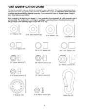
... hardware for shipping purposes. Unless otherwise directed, wait until you identify the small parts used in parenthesis below each assembly stage to the key number of the part, from the PART LIST on page 22. If you cannot find a part in... Nylon Locknut (3) 1/4" Nylon Locknut (2) 1" Retainer (68) 5/16" Nylon Jamnut (87) 5 Cable Clip (53) Important: Some parts may have been pre-assembled for each stage is divided into four stages: 1) frame assembly, 2) arm assembly, 3) cable assembly, and 4) seat assembly. PART IDENTIFICATION CHART This chart is provided to see if it has been pre...
... hardware for shipping purposes. Unless otherwise directed, wait until you identify the small parts used in parenthesis below each assembly stage to the key number of the part, from the PART LIST on page 22. If you cannot find a part in... Nylon Locknut (3) 1/4" Nylon Locknut (2) 1" Retainer (68) 5/16" Nylon Jamnut (87) 5 Cable Clip (53) Important: Some parts may have been pre-assembled for each stage is divided into four stages: 1) frame assembly, 2) arm assembly, 3) cable assembly, and 4) seat assembly. PART IDENTIFICATION CHART This chart is provided to see if it has been pre...
English Manual
Page 7
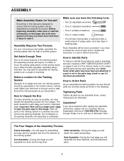
...Two (2) adjustable wrenches • One (1) standard screwdriver • One (1) phillips screwdriver • One (1) rubber mallet • You will be assembled in individual bags. Do not dispose of the training system. Tightening Parts Tighten all parts as possible, we have a socket set, a set of ...parts may want to do otherwise. Refer to it will also need grease or petroleum jelly, a small amount of another person. ASSEMBLY Make Assembly Easier for Yourself Everything in the drawings. Place all parts are found in the location where it to open -end or closed-...
...Two (2) adjustable wrenches • One (1) standard screwdriver • One (1) phillips screwdriver • One (1) rubber mallet • You will be assembled in individual bags. Do not dispose of the training system. Tightening Parts Tighten all parts as possible, we have a socket set, a set of ...parts may want to do otherwise. Refer to it will also need grease or petroleum jelly, a small amount of another person. ASSEMBLY Make Assembly Easier for Yourself Everything in the drawings. Place all parts are found in the location where it to open -end or closed-...
English Manual
Page 8
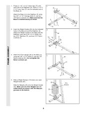
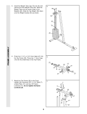
... of the Weights are oriented exactly as shown. 1 21 5 4 73 1 73 27 2. Insert the Weight Guides (62) into the indicated end of the Stabilizer (5). FRAME ASSEMBLY 1. Slide a Weight Bumper (19) down over each end of the Base (4).
... of the Weights are oriented exactly as shown. 1 21 5 4 73 1 73 27 2. Insert the Weight Guides (62) into the indicated end of the Stabilizer (5). FRAME ASSEMBLY 1. Slide a Weight Bumper (19) down over each end of the Base (4).
English Manual
Page 9
... small holes in the Weights (25). Slide the Top Weight (56) down onto the Weight Guides (62) as shown. 5 62 56 63 72 25 FRAME ASSEMBLY 6.
... small holes in the Weights (25). Slide the Top Weight (56) down onto the Weight Guides (62) as shown. 5 62 56 63 72 25 FRAME ASSEMBLY 6.
English Manual
Page 10
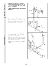
... of each Press Arm (46). Tighten all Nylon Locknuts used in the same manner. 46 17 16 Lubricate 4 21 44 49 46 3 22 17 ARM ASSEMBLY 10 Do not overtighten the Nylon Locknut; the Press Frame must be able to the Weight Guides (62) using a 5/16" x 6" Bolt (60), two 1/2" x 1/2" Spacers (61..." x 2 1/2" Bolts (22) and two 5/16" Nylon Locknuts (3). Attach the 9 Press Frame (17) to the Press Frame (17) using the Bolt and a 3/8" Nylon Locknut (21). FRAME ASSEMBLY 8.
... of each Press Arm (46). Tighten all Nylon Locknuts used in the same manner. 46 17 16 Lubricate 4 21 44 49 46 3 22 17 ARM ASSEMBLY 10 Do not overtighten the Nylon Locknut; the Press Frame must be able to the Weight Guides (62) using a 5/16" x 6" Bolt (60), two 1/2" x 1/2" Spacers (61..." x 2 1/2" Bolts (22) and two 5/16" Nylon Locknuts (3). Attach the 9 Press Frame (17) to the Press Frame (17) using the Bolt and a 3/8" Nylon Locknut (21). FRAME ASSEMBLY 8.
English Manual
Page 11
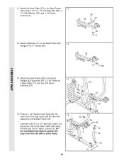
... and a 5/16" Nylon Locknut (3). the Leg Lever must be able to the Seat Frame 11 (36) using a #10 x 1" Screw (80). 78 2 36 11 80 ARM ASSEMBLY 13. Attach the Seat Plate (37) to pivot freely. 36 32 3 36 22 32 29 32 11 Do not overtighten the Nylon Locknut; Press a 1 1/2" Square...
... and a 5/16" Nylon Locknut (3). the Leg Lever must be able to the Seat Frame 11 (36) using a #10 x 1" Screw (80). 78 2 36 11 80 ARM ASSEMBLY 13. Attach the Seat Plate (37) to pivot freely. 36 32 3 36 22 32 29 32 11 Do not overtighten the Nylon Locknut; Press a 1 1/2" Square...
English Manual
Page 12
... to the CABLE DIAGRAM on the Retainers bend toward the Round Outer Cap, as shown in the Top Frame (55) as shown. Important: As you assemble the cables in the groove of the Right Arm is on the Top Frame (55). Hold a Long Cable Trap (50) against the Pulley so that... be able to turn freely. 18. Lubricate both axles on the indicated side. Attach a "V"-Pulley (6) to the bracket (not shown) on the Top Frame (55). Assemble the Right Arm (48, not shown) in the Top Frame using a 3/8" x 2 1/4" Bolt (76) and a 3/8" Nylon Jamnut (67). Attach the "V"-Pulley (6) and the Long Cable Trap...
... to the CABLE DIAGRAM on the Retainers bend toward the Round Outer Cap, as shown in the Top Frame (55) as shown. Important: As you assemble the cables in the groove of the Right Arm is on the Top Frame (55). Hold a Long Cable Trap (50) against the Pulley so that... be able to turn freely. 18. Lubricate both axles on the indicated side. Attach a "V"-Pulley (6) to the bracket (not shown) on the Top Frame (55). Assemble the Right Arm (48, not shown) in the Top Frame using a 3/8" x 2 1/4" Bolt (76) and a 3/8" Nylon Jamnut (67). Attach the "V"-Pulley (6) and the Long Cable Trap...
English Manual
Page 13
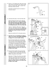
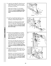
CABLE ASSEMBLY 19. Route the Short Cable (23) around two "V"- 19 Pulleys (6). Remove the 1/2" Nylon Locknut (81) from the 20 rod on the Top Frame with a 1/4" Washer (...
CABLE ASSEMBLY 19. Route the Short Cable (23) around two "V"- 19 Pulleys (6). Remove the 1/2" Nylon Locknut (81) from the 20 rod on the Top Frame with a 1/4" Washer (...
English Manual
Page 14
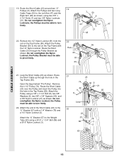
... and the Cable Trap (66) to the Front Upright (42) using a 3/8" x 4 1/4" Bolt (64), a 3/8" Washer (9), and a 3/8" Nylon Locknut (21). Remove the pre-assembled 3 1/2" Pulleys (15) from the Pulley Plates (58). Route the Long Cable (69) around one of the Pulleys. Attach the 3 1/2" Pulley (15) and the Cable Trap...15). Do not overtighten the Nylon Locknuts; the Pulley must be able to turn freely. 26. Do not overtighten the Nylon Locknut; CABLE ASSEMBLY 23. Hold the Long Cable (69) against the Pulley so that the Cable is held securely in place. Do not overtighten the Nylon Locknut...
... and the Cable Trap (66) to the Front Upright (42) using a 3/8" x 4 1/4" Bolt (64), a 3/8" Washer (9), and a 3/8" Nylon Locknut (21). Remove the pre-assembled 3 1/2" Pulleys (15) from the Pulley Plates (58). Route the Long Cable (69) around one of the Pulleys. Attach the 3 1/2" Pulley (15) and the Cable Trap...15). Do not overtighten the Nylon Locknuts; the Pulley must be able to turn freely. 26. Do not overtighten the Nylon Locknut; CABLE ASSEMBLY 23. Hold the Long Cable (69) against the Pulley so that the Cable is held securely in place. Do not overtighten the Nylon Locknut...
English Manual
Page 15
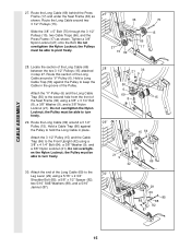
... (15) and the Cable Trap (66) to hold the Long Cable in place. Hold a Cable Trap (66) against the Pulley to turn freely. 29. CABLE ASSEMBLY 27. Tighten a 3/8" Nylon Locknut (21) onto the Bolt. Do not overtighten the Nylon Locknut; the Pulley must be able to keep the Cable in step...
... (15) and the Cable Trap (66) to hold the Long Cable in place. Hold a Cable Trap (66) against the Pulley to turn freely. 29. CABLE ASSEMBLY 27. Tighten a 3/8" Nylon Locknut (21) onto the Bolt. Do not overtighten the Nylon Locknut; the Pulley must be able to keep the Cable in step...
English Manual
Page 16
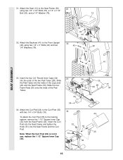
... the Seat Frame (36) 31 using two 1/4" x 3" Bolts (43) and two 1/4" Washers (78). 36 78 33 18 32 43 42 78 43 78 41 SEAT ASSEMBLY 33. Slide the four Foam Pads (30) onto the ends of the two Pad Tubes (28). Attach the Backrest (41) to the training system, remove...
... the Seat Frame (36) 31 using two 1/4" x 3" Bolts (43) and two 1/4" Washers (78). 36 78 33 18 32 43 42 78 43 78 41 SEAT ASSEMBLY 33. Slide the four Foam Pads (30) onto the ends of the two Pad Tubes (28). Attach the Backrest (41) to the training system, remove...
English Manual
Page 17
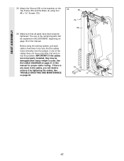
... the 35 Top Frame (55) and the Base (4) using the training system, pull each cable a few times to remove it by tightening the cables. SEAT ASSEMBLY 35. If there is used. See the CABLE DIAGRAM on page 18 of the remaining parts will need to be damaged when heavy weight is...
... the 35 Top Frame (55) and the Base (4) using the training system, pull each cable a few times to remove it by tightening the cables. SEAT ASSEMBLY 35. If there is used. See the CABLE DIAGRAM on page 18 of the remaining parts will need to be damaged when heavy weight is...
English Manual
Page 21
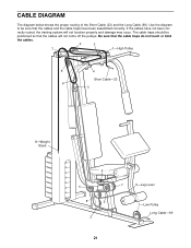
... touch or bind the cables. 2 3 7 1-High Pulley 5 4 Short Cable-23 6 3 8-Weight Stack 6 4 8 5 2 7 9-Leg Lever 1-Low Pulley Long Cable-69 21 If the cables have been assembled correctly. rectly routed, the training system will not come off the pulleys.
... touch or bind the cables. 2 3 7 1-High Pulley 5 4 Short Cable-23 6 3 8-Weight Stack 6 4 8 5 2 7 9-Leg Lever 1-Low Pulley Long Cable-69 21 If the cables have been assembled correctly. rectly routed, the training system will not come off the pulleys.


