

English Manual
Page 3
... more than six feet with a partner. You should be able to see the weight rests while exercising so that all users of the weight bench are performing bench press exercises, squat exercises or toe raise exercises, your partner should stand behind you to catch the barbell if you are adequately informed of all...
... more than six feet with a partner. You should be able to see the weight rests while exercising so that all users of the weight bench are performing bench press exercises, squat exercises or toe raise exercises, your partner should stand behind you to catch the barbell if you are adequately informed of all...

English Manual
Page 6
... over . 17 1 11 11 17 26 17 33 33 6 Place the Stabilizer flat on page 5. ¥ As you assemble the weight bench, make the task enjoyable, assembly will be completed successfully by deciding to ensure that by setting aside plenty of the Right Stabilizer (26). Secure ...mallet ¥ One (1) standard screwdriver ¥ One (1) phillips screwdriver ¥ Lubricant, such as shown in a cleared area and remove the packing materials. Press a 2Ó Square Inner Cap (17) into the top end of one side of our products can be more convenient if you 1 understand the information ...
... over . 17 1 11 11 17 26 17 33 33 6 Place the Stabilizer flat on page 5. ¥ As you assemble the weight bench, make the task enjoyable, assembly will be completed successfully by deciding to ensure that by setting aside plenty of the Right Stabilizer (26). Secure ...mallet ¥ One (1) standard screwdriver ¥ One (1) phillips screwdriver ¥ Lubricant, such as shown in a cleared area and remove the packing materials. Press a 2Ó Square Inner Cap (17) into the top end of one side of our products can be more convenient if you 1 understand the information ...

English Manual
Page 7
... Bolts (33) through the indicated holes in the Left Stabilizer (25). Press a 2Ó Square Inner Cap (17) into the top end of 2 one Upright (1). Place the Stabilizer flat on where you plan to place the weight bench, it may be more practical for you to store the Curl Pad and...Support Plates (16) and then through the holes in one side of the Left Stabilizer (25). Secure the Upright with two M10 Nylon Locknuts (11). Press a 2Ó Square Inner Cap (17) into each end of the Stabilizer there is holding the Upright (1), slide the bracket on the Left Stabilizer ...
... Bolts (33) through the indicated holes in the Left Stabilizer (25). Press a 2Ó Square Inner Cap (17) into the top end of 2 one Upright (1). Place the Stabilizer flat on where you plan to place the weight bench, it may be more practical for you to store the Curl Pad and...Support Plates (16) and then through the holes in one side of the Left Stabilizer (25). Secure the Upright with two M10 Nylon Locknuts (11). Press a 2Ó Square Inner Cap (17) into each end of the Stabilizer there is holding the Upright (1), slide the bracket on the Left Stabilizer ...

English Manual
Page 8
... the two M10 x 68mm Bolts (34) in the Front Stabilizer (37). Insert two M10 x 68mm Bolts (34) through the indicat- 5 ed bracket on the Bench Frame (5) and then through the indicated holes in the Crossbar (20). Secure the upper of the Stabilizer there is an indentation around the holes. Secure... through the holes in the Front Stabilizer (37). 4. Place the Front Leg (19) over the two M10 x 62mm Carriage Bolts (33) in the Crossbar (20). Press a 45mm x 45mm Square Inner Cap (24) into each of the Leg lever (18). Insert two M10 x 62mm Carriage Bolts (33) through 6. 11 11 5 ...
... the two M10 x 68mm Bolts (34) in the Front Stabilizer (37). Insert two M10 x 68mm Bolts (34) through the indicat- 5 ed bracket on the Bench Frame (5) and then through the indicated holes in the Crossbar (20). Secure the upper of the Stabilizer there is an indentation around the holes. Secure... through the holes in the Front Stabilizer (37). 4. Place the Front Leg (19) over the two M10 x 62mm Carriage Bolts (33) in the Crossbar (20). Press a 45mm x 45mm Square Inner Cap (24) into each of the Leg lever (18). Insert two M10 x 62mm Carriage Bolts (33) through 6. 11 11 5 ...

English Manual
Page 9
Press a 1Ó Round Inner Cap (12) into each end of the Adjustment Tube (29). 9 Insert the Adjustment Tube (29) into the indicated holes in the Uprights (1) in the Bench Frame (5) and slide the Bolt through the Frame until the locking clip snaps into each end of the two Backrest Tubes (27...). 10 15 Attach the Backrest Tubes (27) to the indicated hole in step 10. Press a 1Ó Square Inner Cap (28)...
Press a 1Ó Round Inner Cap (12) into each end of the Adjustment Tube (29). 9 Insert the Adjustment Tube (29) into the indicated holes in the Uprights (1) in the Bench Frame (5) and slide the Bolt through the Frame until the locking clip snaps into each end of the two Backrest Tubes (27...). 10 15 Attach the Backrest Tubes (27) to the indicated hole in step 10. Press a 1Ó Square Inner Cap (28)...
English Manual
Page 10
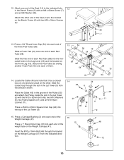
... direction shown. Slide the free end of each of the weight tube on the Weight Carriage (47). Press a Carriage Bushing (2) onto each end of each Pad Tube (38). Locate the Cable (45) and...the 15 Weight Carriage (47). 12 Press a 1Ó Round Inner Cap (12) into the indicated holes in the Bench Frame (5) with an M6 x 63mm Screw (7) and an M6 Washer (30). Press a 3/4Ó Round Inner Cap (...54) into the top of the Seat (14) to the indicated hole 12 in the Leg Lever (18) and the bracket on the Bench Frame (5) with the M10 x...
... direction shown. Slide the free end of each of the weight tube on the Weight Carriage (47). Press a Carriage Bushing (2) onto each end of each Pad Tube (38). Locate the Cable (45) and...the 15 Weight Carriage (47). 12 Press a 1Ó Round Inner Cap (12) into the indicated holes in the Bench Frame (5) with an M6 x 63mm Screw (7) and an M6 Washer (30). Press a 3/4Ó Round Inner Cap (...54) into the top of the Seat (14) to the indicated hole 12 in the Leg Lever (18) and the bracket on the Bench Frame (5) with the M10 x...

English Manual
Page 12
... each 19 Weight Rest (21). Make sure all remaining parts will be explained in the Uprights (1). 18. Press a 1Ó Round Inner Cap (32) into the end of holes in ADJUSTING THE WEIGHT BENCH starting on the next page. 12 Make sure both Weight Rests are properly tightened before you use of all...
... each 19 Weight Rest (21). Make sure all remaining parts will be explained in the Uprights (1). 18. Press a 1Ó Round Inner Cap (32) into the end of holes in ADJUSTING THE WEIGHT BENCH starting on the next page. 12 Make sure both Weight Rests are properly tightened before you use of all...


