Installation Manual
Page 49
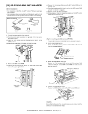
... it on the back of the main unit. 2 4 3 5 5 3 2 * If you need not mount an extended memory, proceed to the MFP control PWB unit. [10] AR-FX8/AR-MM9 INSTALLATION • For installation of AR-FX8, the MFP control PWB unit must have been installed. • Start installation after checking that secure the upper right cabinet and remove the upper...
... it on the back of the main unit. 2 4 3 5 5 3 2 * If you need not mount an extended memory, proceed to the MFP control PWB unit. [10] AR-FX8/AR-MM9 INSTALLATION • For installation of AR-FX8, the MFP control PWB unit must have been installed. • Start installation after checking that secure the upper right cabinet and remove the upper...
Installation Manual
Page 50
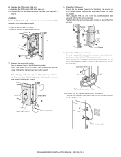
...power connector. Secure the snap band of the connector are securely locked and the connector is not inserted at an angle. 6) Reattach the MFP control PWB unit. Remove the screw that both ends of the FAX interface cable. Connector cover Screw Screws Snap band FAX power connector Screw 10) ...Connect the FAX interface cable to secure the FAX box unit. Grip Upper right cabinet Cut-out portion FAX interface cable AR-M550/M620/M700 INSTALLATION MANUAL (AR-FX8) 10 - 2 Then, remove the cut-out portion for connection with the two screws. Then, connect the FAX power...
...power connector. Secure the snap band of the connector are securely locked and the connector is not inserted at an angle. 6) Reattach the MFP control PWB unit. Remove the screw that both ends of the FAX interface cable. Connector cover Screw Screws Snap band FAX power connector Screw 10) ...Connect the FAX interface cable to secure the FAX box unit. Grip Upper right cabinet Cut-out portion FAX interface cable AR-M550/M620/M700 INSTALLATION MANUAL (AR-FX8) 10 - 2 Then, remove the cut-out portion for connection with the two screws. Then, connect the FAX power...


