Owner's Manual
Page 6
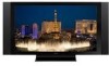
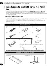
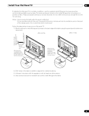
...screwdriver when mounting the speaker and attaching the stand. The PRO-151FD and PRO-111FD shipments have slightly different pieces. If an item is a list of this manual. 1.1 Flat Panel TV Shipment Checklist In addition to the flat panel TV, there are several accessories included to the top right ...of the rear panel) Bracket (for 50") 6 En Below is missing, please contact your installer to the ELITE Series Flat Panel TVs The Pioneer ELITE Series Flat Panel TV models include the 60-inch PRO-151FD and the 50-inch PRO-111FD ...
...screwdriver when mounting the speaker and attaching the stand. The PRO-151FD and PRO-111FD shipments have slightly different pieces. If an item is a list of this manual. 1.1 Flat Panel TV Shipment Checklist In addition to the flat panel TV, there are several accessories included to the top right ...of the rear panel) Bracket (for 50") 6 En Below is missing, please contact your installer to the ELITE Series Flat Panel TVs The Pioneer ELITE Series Flat Panel TV models include the 60-inch PRO-151FD and the 50-inch PRO-111FD ...
Owner's Manual
Page 7
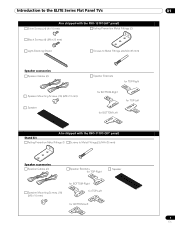
Introduction to the ELITE Series Flat Panel TVs 01 Also shipped with the PRO-151FD (60" panel) Silver Screws (4) (4×10 mm) Falling Prevention Metal Fittings (2) Black Screws (4) (M6×20 mm) Light-Blocking Shield Screws to Metal Fittings (4) (M4&#... Screws (16) (M5×10 mm) Speaker Speaker Brackets for TOP-Right for BOTTOM-Right for TOP-Left for BOTTOM-Left Also shipped with the PRO-111FD (50" panel) Stand kit Falling Prevention Metal Fittings (2) Screws to Metal Fittings(2) (M4×35 mm) Speaker accessories Speaker Cables (2) Speaker Brackets for TOP-Right Speaker...
Introduction to the ELITE Series Flat Panel TVs 01 Also shipped with the PRO-151FD (60" panel) Silver Screws (4) (4×10 mm) Falling Prevention Metal Fittings (2) Black Screws (4) (M6×20 mm) Light-Blocking Shield Screws to Metal Fittings (4) (M4&#... Screws (16) (M5×10 mm) Speaker Speaker Brackets for TOP-Right for BOTTOM-Right for TOP-Left for BOTTOM-Left Also shipped with the PRO-111FD (50" panel) Stand kit Falling Prevention Metal Fittings (2) Screws to Metal Fittings(2) (M4×35 mm) Speaker accessories Speaker Cables (2) Speaker Brackets for TOP-Right Speaker...
Owner's Manual
Page 8
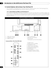
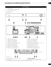
... sheet located near the panel's terminal compartment to identify the various options. ELITE Series Models: Face of the Panel (left side) 8 13 14 9 15 (PRO-151FD) 1 23 45 7 4 -Room Light sensor 5 -Remote Control sensor 6 -Color Sensor 7 -Bezel (some call it the front frame) 8 -USB ...TV You can operate your flat panel TV from the panel buttons or with more buttons, toggles, and ports on the lower front bezel with the remote control. Refer to the drawings below for specific locations and functions. STANDBY indicator 3 - SLEEP indicator Command Side of Panel 6 (PRO-111FD...
... sheet located near the panel's terminal compartment to identify the various options. ELITE Series Models: Face of the Panel (left side) 8 13 14 9 15 (PRO-151FD) 1 23 45 7 4 -Room Light sensor 5 -Remote Control sensor 6 -Color Sensor 7 -Bezel (some call it the front frame) 8 -USB ...TV You can operate your flat panel TV from the panel buttons or with more buttons, toggles, and ports on the lower front bezel with the remote control. Refer to the drawings below for specific locations and functions. STANDBY indicator 3 - SLEEP indicator Command Side of Panel 6 (PRO-111FD...
Owner's Manual
Page 9
...IR REPEATER OUT terminal 21 -PC INPUT terminal (Audio) 22 -CONTROL OUT terminal 23 -DIGITAL OUT terminal (Optical) 24 -SPEAKERS (right/left) terminal (PRO-151FD) (lower bank) 25 26 27 28 25 -Speakers (R) terminal (speaker side) 26 -Color Sensor 27 -Power On button 28 -Speakers (L) terminal (...speaker side) Terminals on side and rear panels are common to the ELITE Series Flat Panel TVs 01 1 - Introduction to both ELITE models. 9 En INPUT 5 terminal (HDMI) 8 - AC In terminal (upper bank) Back of the Panel 1 5 (middle ...
...IR REPEATER OUT terminal 21 -PC INPUT terminal (Audio) 22 -CONTROL OUT terminal 23 -DIGITAL OUT terminal (Optical) 24 -SPEAKERS (right/left) terminal (PRO-151FD) (lower bank) 25 26 27 28 25 -Speakers (R) terminal (speaker side) 26 -Color Sensor 27 -Power On button 28 -Speakers (L) terminal (...speaker side) Terminals on side and rear panels are common to the ELITE Series Flat Panel TVs 01 1 - Introduction to both ELITE models. 9 En INPUT 5 terminal (HDMI) 8 - AC In terminal (upper bank) Back of the Panel 1 5 (middle ...
Owner's Manual
Page 14
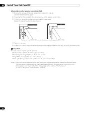
Pioneer recommends working with the shipment. Regardless of the mounting holes and/or supplied bolts. Use installation accessories and parts included with a qualified installer whenever possible. Check with your flat panel TV using a combination of the mounting method, anchor or secure your...panel needs a solid surface and some sort of bolt. Rear view (PRO-151FD) Mounting hole Mounting hole Side view Mounting surface Mounting bracket (or equivalent item) M8 screw 12 mm to 18 mm (0.5 inches to 0.7 inches) Rear view (PRO-111FD) W Mounting hole W T W W Mounting hole W T W Note...
Pioneer recommends working with the shipment. Regardless of the mounting holes and/or supplied bolts. Use installation accessories and parts included with a qualified installer whenever possible. Check with your flat panel TV using a combination of the mounting method, anchor or secure your...panel needs a solid surface and some sort of bolt. Rear view (PRO-151FD) Mounting hole Mounting hole Side view Mounting surface Mounting bracket (or equivalent item) M8 screw 12 mm to 18 mm (0.5 inches to 0.7 inches) Rear view (PRO-111FD) W Mounting hole W T W W Mounting hole W T W Note...
Owner's Manual
Page 16
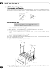
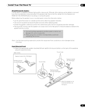
...Detach the Speaker" on page 19 for the PRO-151FD. Screws (4 x 10 mm: silver) Screws (4 x 10 mm: silver) Rear Front Completed stand Sheet Base cover Note: Assemble the stand with the Pioneer table top stand (stand) attached. For PRO-111FD, attach the falling prevention metal fittings after placing ...the panel to stand upright. (PRO-111FD) Installation screws (M4 × 35 mm: black) Falling prevention metal fitting Attach the Stand to the Panel Do not handle the flat panel TV on a soft cloth to Step 7. 4 ) Turn the base cover ...
...Detach the Speaker" on page 19 for the PRO-151FD. Screws (4 x 10 mm: silver) Screws (4 x 10 mm: silver) Rear Front Completed stand Sheet Base cover Note: Assemble the stand with the Pioneer table top stand (stand) attached. For PRO-111FD, attach the falling prevention metal fittings after placing ...the panel to stand upright. (PRO-111FD) Installation screws (M4 × 35 mm: black) Falling prevention metal fitting Attach the Stand to the Panel Do not handle the flat panel TV on a soft cloth to Step 7. 4 ) Turn the base cover ...
Owner's Manual
Page 17
... 7 ) After assembling the stand, attach the falling prevention metal fittings using the installation screws. (PRO-151FD) Installation screws (M4 x 35 mm: black) Falling prevention metal fitting 8 ) With the flat panel TV still face down . 9 ) With the assistance of at least one other person, lift the panel upright then move ... to position. 17 En Installation bolts (M6 x 20 mm) Installation bolts (M6 x 20 mm) Insert the stand supports into the flat panel TV so that the arrow marked "FRONT/FACE AVANT" on the bottom of the stand points down , insert the stand's supports into the bottom of...
... 7 ) After assembling the stand, attach the falling prevention metal fittings using the installation screws. (PRO-151FD) Installation screws (M4 x 35 mm: black) Falling prevention metal fitting 8 ) With the flat panel TV still face down . 9 ) With the assistance of at least one other person, lift the panel upright then move ... to position. 17 En Installation bolts (M6 x 20 mm) Installation bolts (M6 x 20 mm) Insert the stand supports into the flat panel TV so that the arrow marked "FRONT/FACE AVANT" on the bottom of the stand points down , insert the stand's supports into the bottom of...
Owner's Manual
Page 19
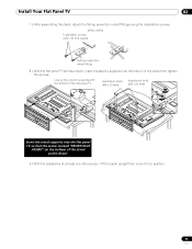
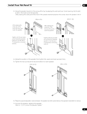
... damage. • Placing a CRT monitor near the speaker can damage the unit or cause a fire. • When using the supplied screws. (PRO-151FD) Screw holes Speaker bracket (For TOP-Right) Speaker bracket (For BOTTOM-Right) Screw holes Speaker bracket (For TOP-Right) Speaker bracket (For BOTTOM-Right...device can cause a blur on the back of the speakers using tone control to the top and bottom on the flat panel TV. Stand-Mounted Panel 1 ) Attach the appropriate speaker brackets (left and right) to increase treble, avoid overamplifying the volume. Although other damage...
... damage. • Placing a CRT monitor near the speaker can damage the unit or cause a fire. • When using the supplied screws. (PRO-151FD) Screw holes Speaker bracket (For TOP-Right) Speaker bracket (For BOTTOM-Right) Screw holes Speaker bracket (For TOP-Right) Speaker bracket (For BOTTOM-Right...device can cause a blur on the back of the speakers using tone control to the top and bottom on the flat panel TV. Stand-Mounted Panel 1 ) Attach the appropriate speaker brackets (left and right) to increase treble, avoid overamplifying the volume. Although other damage...
Owner's Manual
Page 21
... the two screws at the top by passing the wide part over it . (PRO-151FD) (PRO-111FD) After passing the wide part of the hole over the screw, lower the speaker. Refer to the flat panel TV temporarily (one place bottom). screw in the lower screw temporarily. Install Your Flat ...Panel TV 02 3 ) Hang the speaker bracket on the screw at the top and bottom for each speaker. (PRO-151FD) (PRO-111FD) 6 ) Pass the supplied speaker cable between the speaker and the panel (below the speaker bracket) from ...
... the two screws at the top by passing the wide part over it . (PRO-151FD) (PRO-111FD) After passing the wide part of the hole over the screw, lower the speaker. Refer to the flat panel TV temporarily (one place bottom). screw in the lower screw temporarily. Install Your Flat ...Panel TV 02 3 ) Hang the speaker bracket on the screw at the top and bottom for each speaker. (PRO-151FD) (PRO-111FD) 6 ) Pass the supplied speaker cable between the speaker and the panel (below the speaker bracket) from ...
Owner's Manual
Page 22
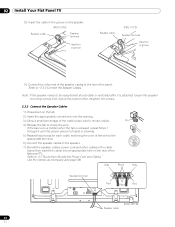
... Press down on the tab. 2 ) Insert the appropriately colored wire into an appropriate hole on the speaker. (PRO-151FD) Speaker cable Speaker terminal Insertion in groove Speaker cable (PRO-111FD) Speaker terminal Insertion in the cable clamp then insert the clamp into the opening. 3 ) Allow a small percentage... of the cable's bare wire to remain visible. Refer to clamp the wire. 02 Install Your Flat Panel TV 8 ) Insert the...
... Press down on the tab. 2 ) Insert the appropriately colored wire into an appropriate hole on the speaker. (PRO-151FD) Speaker cable Speaker terminal Insertion in groove Speaker cable (PRO-111FD) Speaker terminal Insertion in the cable clamp then insert the clamp into the opening. 3 ) Allow a small percentage... of the cable's bare wire to remain visible. Refer to clamp the wire. 02 Install Your Flat Panel TV 8 ) Insert the...
Owner's Manual
Page 23
... cable's bare wire touches other than the speakers specified. (PRO-111FD) 2.3 Wall/Ceiling Mounting Lay the 50" panel down on a raised surface then remove the stand. Installation bolts (1) Installation bolts (2) 23 En Install Your Flat Panel TV 02 PRO-151FD with the power cord plugged in can result in the power.... Plug in an electrical short causing malfunction or damage to the system. • Do not connect any devices to the flat panel TV, unplug the panel from the power outlet. Connecting the speaker cable with the speaker installed Black Gray Black Red Cable ...
... cable's bare wire touches other than the speakers specified. (PRO-111FD) 2.3 Wall/Ceiling Mounting Lay the 50" panel down on a raised surface then remove the stand. Installation bolts (1) Installation bolts (2) 23 En Install Your Flat Panel TV 02 PRO-151FD with the power cord plugged in can result in the power.... Plug in an electrical short causing malfunction or damage to the system. • Do not connect any devices to the flat panel TV, unplug the panel from the power outlet. Connecting the speaker cable with the speaker installed Black Gray Black Red Cable ...
Owner's Manual
Page 25
... the flat panel TV on a table or platform, use bare wires for metal fittings and screws on a wooden surface. If any part of the display panel, fire or electrical shock could result. These screws should have a nominal diameter of the table using the panel stand to determine placement. (PRO-151FD) (PRO-111FD) 8 mm to 15... 4 mm (5/32 inch) and are at least one other person. 4 ) Use wood screws (not included) to secure the metal fittings to secure your flat panel TV. 1 ) Mark locations for the cord. Follow the steps below to the table. 25 En
... the flat panel TV on a table or platform, use bare wires for metal fittings and screws on a wooden surface. If any part of the display panel, fire or electrical shock could result. These screws should have a nominal diameter of the table using the panel stand to determine placement. (PRO-151FD) (PRO-111FD) 8 mm to 15... 4 mm (5/32 inch) and are at least one other person. 4 ) Use wood screws (not included) to secure the metal fittings to secure your flat panel TV. 1 ) Mark locations for the cord. Follow the steps below to the table. 25 En

Owner's Manual
Page 27
... the bottom of the front panel. 27 En When using the speaker brackets. The bracket is for PRO-151FD panel but do NOT plug in to the power outlet. Use the removed screws again. (Bracket for PRO-111FD. 4 ) Fasten the screws. 5 ) Connect the cable to the color sensor terminal on the ... properly, attach it in a high- Install Your Flat Panel TV 02 Attach the Color Sensor to the Rear Panel Methods of attaching the color sensor to the rear panel differ depending on the rear upper bank but the procedure is the same for PRO-151FD) 2 ) Loosen the upper two (2) speaker bracket screws. ...
... the bottom of the front panel. 27 En When using the speaker brackets. The bracket is for PRO-151FD panel but do NOT plug in to the power outlet. Use the removed screws again. (Bracket for PRO-111FD. 4 ) Fasten the screws. 5 ) Connect the cable to the color sensor terminal on the ... properly, attach it in a high- Install Your Flat Panel TV 02 Attach the Color Sensor to the Rear Panel Methods of attaching the color sensor to the rear panel differ depending on the rear upper bank but the procedure is the same for PRO-151FD) 2 ) Loosen the upper two (2) speaker bracket screws. ...
Owner's Manual
Page 28
When using it to the front panel. The bracket is for PRO-151FD panel but do NOT plug in a hightemperature environment, attach the color ...Use the removed screws again. 2 ) Finger tighten the supplied color sensor screws in place. 02 Install Your Flat Panel TV (when side-mounted speakers are not installed) 1 ) Remove the screws of the sensor window • if the ...light falling on the rear upper bank but the procedure is the same for PRO-111FD. 4 ) Fasten the screws. 5 ) Connect the cable to the color sensor terminal on the sensor window and the ...
When using it to the front panel. The bracket is for PRO-151FD panel but do NOT plug in a hightemperature environment, attach the color ...Use the removed screws again. 2 ) Finger tighten the supplied color sensor screws in place. 02 Install Your Flat Panel TV (when side-mounted speakers are not installed) 1 ) Remove the screws of the sensor window • if the ...light falling on the rear upper bank but the procedure is the same for PRO-111FD. 4 ) Fasten the screws. 5 ) Connect the cable to the color sensor terminal on the sensor window and the ...
Owner's Manual
Page 32
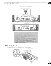
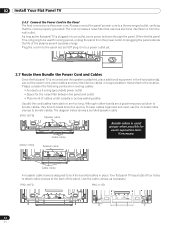
...or are a good temporary solution to bundle cables, they tend to the back of the plasma as well as necessary. T T W W 2.7 Route then Bundle the Power Cord and Cables Once the flat panel TV is mounted and the speaker is not going to a three-pronged outlet, verifying that ... Please consider the following points when routing cables: • Access to the Panel The final connection is properly grounded. PRO-151FD PRO-111FD 32 En When the flat panel TV is attached, place additional equipment in place. Always connect the panel's power cord to be used for the location. Although...
...or are a good temporary solution to bundle cables, they tend to the back of the plasma as well as necessary. T T W W 2.7 Route then Bundle the Power Cord and Cables Once the flat panel TV is mounted and the speaker is not going to a three-pronged outlet, verifying that ... Please consider the following points when routing cables: • Access to the Panel The final connection is properly grounded. PRO-151FD PRO-111FD 32 En When the flat panel TV is attached, place additional equipment in place. Always connect the panel's power cord to be used for the location. Although...

Owner's Manual
Page 124
...flat panel TV. For details on the display for an extended time period, when the image changes or the unit is mostly composed of time can I do I feed a PC signal through the PRO-151FD/111FD's HDMI input...or aerosol cleaners on the screen can let moisture seep into the panel. Why won't my Pioneer flat panel TV turn the panel's a off for Signal Type in the panel again after checking the versions.... cropped when I clean my flat panel TV? To clean the screen surface, gently wipe it back on ? If you rub too hard) can check the version of plasma technology. If the light still blinks, ...
...flat panel TV. For details on the display for an extended time period, when the image changes or the unit is mostly composed of time can I do I feed a PC signal through the PRO-151FD/111FD's HDMI input...or aerosol cleaners on the screen can let moisture seep into the panel. Why won't my Pioneer flat panel TV turn the panel's a off for Signal Type in the panel again after checking the versions.... cropped when I clean my flat panel TV? To clean the screen surface, gently wipe it back on ? If you rub too hard) can check the version of plasma technology. If the light still blinks, ...
Owner's Manual
Page 135
... a cable operator's enhanced program guide and dataenhanced television services may cause undesired operation. Consult the dealer or an experienced radio/TV technician for a long period of the following two conditions: (1) This device may invalidate the user's right to +104 &#... call your cable operator is subject to radio communications. Product Name: Flat Panel TV Model Number: PRO-151FD/PRO-111FD Product Category: Class B Personal Computers & Peripherals Responsible Party Name: PIONEER ELECTRONICS SERVICE, INC. This equipment generates, uses, and can be unplugged from...
... a cable operator's enhanced program guide and dataenhanced television services may cause undesired operation. Consult the dealer or an experienced radio/TV technician for a long period of the following two conditions: (1) This device may invalidate the user's right to +104 &#... call your cable operator is subject to radio communications. Product Name: Flat Panel TV Model Number: PRO-151FD/PRO-111FD Product Category: Class B Personal Computers & Peripherals Responsible Party Name: PIONEER ELECTRONICS SERVICE, INC. This equipment generates, uses, and can be unplugged from...
Owner's Manual
Page 145
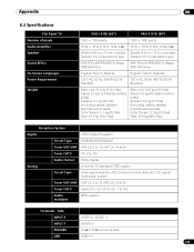
Appendix 08 8.3 Specifications Flat Panel TV Number of pixels Audio Amplifier Speaker Sound Effect On-Screen Languages Power Requirement Weight PRO-151FD (60") PRO-111FD (50") 1920 × 1080 pixels 1920 × 1080 pixels 18 W + 18 W (1 kHz, 10 %, 6 Ω) 18 W + 18 W (1 kHz, 10 %, 6 Ω) Woofer: 4.8 cm ...lbs) (including cables, speaker brackets and screws) Color Sensor: 0.1 kg (0.2 lbs) Total: 39.9 kg (88.0 lbs) Reception System Digital ATSC Digital TV system Circuit Type 8VSB/64QAM/256QAM Tuner VHF/UHF VHF Ch. 2 to 13 UHF Ch. 14 to 69 Tuner CATV Ch. 2 to 135 Audio format...
Appendix 08 8.3 Specifications Flat Panel TV Number of pixels Audio Amplifier Speaker Sound Effect On-Screen Languages Power Requirement Weight PRO-151FD (60") PRO-111FD (50") 1920 × 1080 pixels 1920 × 1080 pixels 18 W + 18 W (1 kHz, 10 %, 6 Ω) 18 W + 18 W (1 kHz, 10 %, 6 Ω) Woofer: 4.8 cm ...lbs) (including cables, speaker brackets and screws) Color Sensor: 0.1 kg (0.2 lbs) Total: 39.9 kg (88.0 lbs) Reception System Digital ATSC Digital TV system Circuit Type 8VSB/64QAM/256QAM Tuner VHF/UHF VHF Ch. 2 to 13 UHF Ch. 14 to 69 Tuner CATV Ch. 2 to 135 Audio format...
Owner's Manual
Page 146
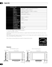
08 Appendix Terminals - Dimensions PRO-151FD (60" panel) 93 (3-21/32) 1677 (66-1/32) 93 (3-21/32) PRO-111FD (50" panel) 1445 (56-7/8) 723 (28-15/32) 788 (73818-1/32) 876 (34-1/2) 953 (37-17/32) 14 (9/16) 14 (9/16) 430 (16-15/16) 146 ...
08 Appendix Terminals - Dimensions PRO-151FD (60" panel) 93 (3-21/32) 1677 (66-1/32) 93 (3-21/32) PRO-111FD (50" panel) 1445 (56-7/8) 723 (28-15/32) 788 (73818-1/32) 876 (34-1/2) 953 (37-17/32) 14 (9/16) 14 (9/16) 430 (16-15/16) 146 ...


