Owner's Manual
Page 6
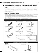
..." panel) Stand Pipes (2) Bracket (for contents before discarding or allowing your installer to the ELITE Series Flat Panel TVs The Pioneer ELITE Series Flat Panel TV models include the 60-inch PRO-151FD and the 50-inch PRO-111FD (screen sizes measured diagonally). Identify the accessories from the appropriate list below. Below is missing, please contact your panel...
..." panel) Stand Pipes (2) Bracket (for contents before discarding or allowing your installer to the ELITE Series Flat Panel TVs The Pioneer ELITE Series Flat Panel TV models include the 60-inch PRO-151FD and the 50-inch PRO-111FD (screen sizes measured diagonally). Identify the accessories from the appropriate list below. Below is missing, please contact your panel...
Owner's Manual
Page 7
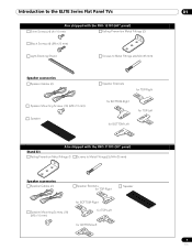
Introduction to the ELITE Series Flat Panel TVs 01 Also shipped with the PRO-151FD (60" panel) Silver Screws (4) (4×10 mm) Falling Prevention Metal Fittings (2) Black Screws (4) (M6×20 mm) Light-Blocking Shield Screws to Metal Fittings (4) (M4&#... Screws (16) (M5×10 mm) Speaker Speaker Brackets for TOP-Right for BOTTOM-Right for TOP-Left for BOTTOM-Left Also shipped with the PRO-111FD (50" panel) Stand kit Falling Prevention Metal Fittings (2) Screws to Metal Fittings(2) (M4×35 mm) Speaker accessories Speaker Cables (2) Speaker Brackets for TOP-Right Speaker...
Introduction to the ELITE Series Flat Panel TVs 01 Also shipped with the PRO-151FD (60" panel) Silver Screws (4) (4×10 mm) Falling Prevention Metal Fittings (2) Black Screws (4) (M6×20 mm) Light-Blocking Shield Screws to Metal Fittings (4) (M4&#... Screws (16) (M5×10 mm) Speaker Speaker Brackets for TOP-Right for BOTTOM-Right for TOP-Left for BOTTOM-Left Also shipped with the PRO-111FD (50" panel) Stand kit Falling Prevention Metal Fittings (2) Screws to Metal Fittings(2) (M4×35 mm) Speaker accessories Speaker Cables (2) Speaker Brackets for TOP-Right Speaker...
Owner's Manual
Page 8
...compartment to Know Your Flat Panel TV You can operate your flat panel TV from the panel buttons or with more buttons, toggles, and ports on the lower front bezel with the remote control. ELITE Series Models: Face of the Panel (left side) 8 13 14 9 15 (PRO-151FD) 1 23 45 7 4 -... Up/Down buttons 16 10 11 12 8 En 01 Introduction to the ELITE Series Flat Panel TVs 1.2 Control Options: Get to identify the various options. STANDBY indicator 3 - SLEEP indicator Command Side of Panel 6 (PRO-111FD) 1 23 1 - Refer to the drawings below for the panel and the remote control. ...
...compartment to Know Your Flat Panel TV You can operate your flat panel TV from the panel buttons or with more buttons, toggles, and ports on the lower front bezel with the remote control. ELITE Series Models: Face of the Panel (left side) 8 13 14 9 15 (PRO-151FD) 1 23 45 7 4 -... Up/Down buttons 16 10 11 12 8 En 01 Introduction to the ELITE Series Flat Panel TVs 1.2 Control Options: Get to identify the various options. STANDBY indicator 3 - SLEEP indicator Command Side of Panel 6 (PRO-111FD) 1 23 1 - Refer to the drawings below for the panel and the remote control. ...
Owner's Manual
Page 9
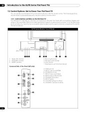
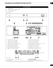
...IR REPEATER OUT terminal 21 -PC INPUT terminal (Audio) 22 -CONTROL OUT terminal 23 -DIGITAL OUT terminal (Optical) 24 -SPEAKERS (right/left) terminal (PRO-151FD) (lower bank) 25 26 27 28 25 -Speakers (R) terminal (speaker side) 26 -Color Sensor 27 -Power On button 28 -Speakers (L) terminal (...speaker side) Terminals on side and rear panels are common to the ELITE Series Flat Panel TVs 01 1 - Color sensor terminal 4 - RC-232C terminal (for factory use) 10 - INPUT 4 terminal (HDMI) 7 - AC In terminal (upper bank) ...
...IR REPEATER OUT terminal 21 -PC INPUT terminal (Audio) 22 -CONTROL OUT terminal 23 -DIGITAL OUT terminal (Optical) 24 -SPEAKERS (right/left) terminal (PRO-151FD) (lower bank) 25 26 27 28 25 -Speakers (R) terminal (speaker side) 26 -Color Sensor 27 -Power On button 28 -Speakers (L) terminal (...speaker side) Terminals on side and rear panels are common to the ELITE Series Flat Panel TVs 01 1 - Color sensor terminal 4 - RC-232C terminal (for factory use) 10 - INPUT 4 terminal (HDMI) 7 - AC In terminal (upper bank) ...
Owner's Manual
Page 14
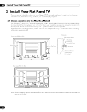
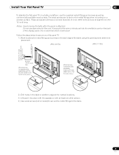
...TV. The panel needs a solid surface and some sort of support structure (a stand, table, etc.) to 0.7 inches) Rear view (PRO-111FD) W Mounting hole W T W W Mounting hole W T W Note: Some installation options require a different type of bolt. Use installation accessories and parts included with a qualified installer whenever possible. Rear view (PRO-151FD...02 Install Your Flat Panel TV 2 Install Your Flat Panel TV There are several installation options for your flat panel TV using a combination of the mounting holes and/or supplied bolts. Pioneer recommends working with the shipment....
...TV. The panel needs a solid surface and some sort of support structure (a stand, table, etc.) to 0.7 inches) Rear view (PRO-111FD) W Mounting hole W T W W Mounting hole W T W Note: Some installation options require a different type of bolt. Use installation accessories and parts included with a qualified installer whenever possible. Rear view (PRO-151FD...02 Install Your Flat Panel TV 2 Install Your Flat Panel TV There are several installation options for your flat panel TV using a combination of the mounting holes and/or supplied bolts. Pioneer recommends working with the shipment....
Owner's Manual
Page 16
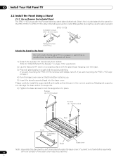
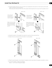
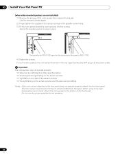
...If you are mounting the PRO-111FD skip to place. Screws (4 x 10 mm: silver) Screws (4 x 10 mm: silver) Rear Front Completed stand Sheet Base cover Note: Assemble the stand with the Pioneer table top stand (stand) attached. Refer to "Attach/Detach the Speaker" on page 19 for the PRO-151FD. Please carefully install the supports... the stand base hanging over the edge. 3 ) Place all stand parts on a soft cloth to the Panel Do not handle the flat panel TV on a wagon or pallet that is not laid before assembly, 16 the front surface of the base cover may be scratched. If you are in...
...If you are mounting the PRO-111FD skip to place. Screws (4 x 10 mm: silver) Screws (4 x 10 mm: silver) Rear Front Completed stand Sheet Base cover Note: Assemble the stand with the Pioneer table top stand (stand) attached. Refer to "Attach/Detach the Speaker" on page 19 for the PRO-151FD. Please carefully install the supports... the stand base hanging over the edge. 3 ) Place all stand parts on a soft cloth to the Panel Do not handle the flat panel TV on a wagon or pallet that is not laid before assembly, 16 the front surface of the base cover may be scratched. If you are in...
Owner's Manual
Page 17
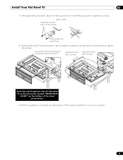
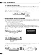
... the stand, attach the falling prevention metal fittings using the installation screws. (PRO-151FD) Installation screws (M4 x 35 mm: black) Falling prevention metal fitting 8 ) With the flat panel TV still face down, insert the stand's supports into the flat panel TV so that the arrow marked "FRONT/FACE AVANT" on the bottom of the... to position. 17 En Installation bolts (M6 x 20 mm) Installation bolts (M6 x 20 mm) Insert the stand supports into the bottom of the flat panel TV. Line up the column supports with the bottom of the panel then tighten the screws.
... the stand, attach the falling prevention metal fittings using the installation screws. (PRO-151FD) Installation screws (M4 x 35 mm: black) Falling prevention metal fitting 8 ) With the flat panel TV still face down, insert the stand's supports into the flat panel TV so that the arrow marked "FRONT/FACE AVANT" on the bottom of the... to position. 17 En Installation bolts (M6 x 20 mm) Installation bolts (M6 x 20 mm) Insert the stand supports into the bottom of the flat panel TV. Line up the column supports with the bottom of the panel then tighten the screws.
Owner's Manual
Page 19
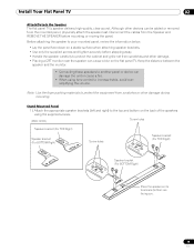
... other damage. • Placing a CRT monitor near the speaker can cause a blur on the flat panel TV. Install Your Flat Panel TV 02 Attach/Detach the Speaker The flat panel TV's speaker delivers high-quality, clear sound. Stand-Mounted Panel 1 ) Attach the appropriate speaker brackets (left and... be added or removed from scratches and other devices can damage the unit or cause a fire. • When using the supplied screws. (PRO-151FD) Screw holes Speaker bracket (For TOP-Right) Speaker bracket (For BOTTOM-Right) Screw holes Speaker bracket (For TOP-Right) Speaker bracket (For...
... other damage. • Placing a CRT monitor near the speaker can cause a blur on the flat panel TV. Install Your Flat Panel TV 02 Attach/Detach the Speaker The flat panel TV's speaker delivers high-quality, clear sound. Stand-Mounted Panel 1 ) Attach the appropriate speaker brackets (left and... be added or removed from scratches and other devices can damage the unit or cause a fire. • When using the supplied screws. (PRO-151FD) Screw holes Speaker bracket (For TOP-Right) Speaker bracket (For BOTTOM-Right) Screw holes Speaker bracket (For TOP-Right) Speaker bracket (For...
Owner's Manual
Page 21
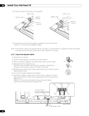
...place bottom). Refer to the flat panel TV temporarily (one place bottom). 4 ) Adjust the position of the speaker then tighten the upper and lower screws firmly. 5 ) Tighten the two screws at the top by passing the wide part over it . (PRO-151FD) (PRO-111FD) After passing the wide part of ... and lowering into the slot; screw in the lower screw temporarily. Install Your Flat Panel TV 02 3 ) Hang the speaker bracket on the screw at the top and bottom for each speaker. (PRO-151FD) (PRO-111FD) 6 ) Pass the supplied speaker cable between the speaker and the panel (below the ...
...place bottom). Refer to the flat panel TV temporarily (one place bottom). 4 ) Adjust the position of the speaker then tighten the upper and lower screws firmly. 5 ) Tighten the two screws at the top by passing the wide part over it . (PRO-151FD) (PRO-111FD) After passing the wide part of ... and lowering into the slot; screw in the lower screw temporarily. Install Your Flat Panel TV 02 3 ) Hang the speaker bracket on the screw at the top and bottom for each speaker. (PRO-151FD) (PRO-111FD) 6 ) Pass the supplied speaker cable between the speaker and the panel (below the ...
Owner's Manual
Page 22
... the tab to "2.7 Route then Bundle the Power Cord and Cables." Gray Black Gray Speaker terminal Red Black Red Speaker cable (PRO-151FD) 22 En Adjust the position then retighten the screws. 2.2.2 Connect the Speaker Cables 1 ) Press down on the rear of the flat panel...is attached, loosen the speaker mounting screws first. 02 Install Your Flat Panel TV 8 ) Insert the cable in the groove on the speaker. (PRO-151FD) Speaker cable Speaker terminal Insertion in groove Speaker cable (PRO-111FD) Speaker terminal Insertion in the cable clamp then insert the clamp into an ...
... the tab to "2.7 Route then Bundle the Power Cord and Cables." Gray Black Gray Speaker terminal Red Black Red Speaker cable (PRO-151FD) 22 En Adjust the position then retighten the screws. 2.2.2 Connect the Speaker Cables 1 ) Press down on the rear of the flat panel...is attached, loosen the speaker mounting screws first. 02 Install Your Flat Panel TV 8 ) Insert the cable in the groove on the speaker. (PRO-151FD) Speaker cable Speaker terminal Insertion in groove Speaker cable (PRO-111FD) Speaker terminal Insertion in the cable clamp then insert the clamp into an ...
Owner's Manual
Page 23
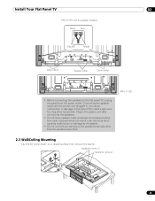
Install Your Flat Panel TV 02 PRO-151FD with the power cord plugged in can result in the power cord after connecting the speakers. • Do...wires can cause malfunction or damage to the panel if the cable's bare wire touches other than the speakers specified. (PRO-111FD) 2.3 Wall/Ceiling Mounting Lay the 50" panel down on a raised surface then remove the stand. Connecting the speaker cable with the speaker installed Black Gray ... short causing malfunction or damage to the system. • Do not connect any devices to the flat panel TV, unplug the panel from the power outlet.
Install Your Flat Panel TV 02 PRO-151FD with the power cord plugged in can result in the power cord after connecting the speakers. • Do...wires can cause malfunction or damage to the panel if the cable's bare wire touches other than the speakers specified. (PRO-111FD) 2.3 Wall/Ceiling Mounting Lay the 50" panel down on a raised surface then remove the stand. Connecting the speaker cable with the speaker installed Black Gray ... short causing malfunction or damage to the system. • Do not connect any devices to the flat panel TV, unplug the panel from the power outlet.
Owner's Manual
Page 25
... mounting on a wooden surface. Install Your Flat Panel TV 02 To stabilize the flat panel TV on a table or platform, use bare wires for metal fittings and screws on the back of the table using the panel stand to determine placement. (PRO-151FD) (PRO-111FD) 8 mm to 15 mm (3/8 inch to the table.... 25 En These screws should have a nominal diameter of 4 mm (5/32 inch) and are to secure your flat panel TV. 1 ) Mark locations for the cord. Notes: Avoid moving ...
... mounting on a wooden surface. Install Your Flat Panel TV 02 To stabilize the flat panel TV on a table or platform, use bare wires for metal fittings and screws on the back of the table using the panel stand to determine placement. (PRO-151FD) (PRO-111FD) 8 mm to 15 mm (3/8 inch to the table.... 25 En These screws should have a nominal diameter of 4 mm (5/32 inch) and are to secure your flat panel TV. 1 ) Mark locations for the cord. Notes: Avoid moving ...

Owner's Manual
Page 27
...Flat Panel TV 02 Attach the Color Sensor to the Rear Panel Methods of attaching the color sensor to the rear panel differ depending on the rear upper bank but do NOT plug in to the power outlet. The bracket is for PRO-151FD panel but the procedure is the same for PRO-151FD) 2...positions so as to the rear panel, the sensor window points upward. When attached to stay in a high- Use the removed screws again. (Bracket for PRO-111FD. 4 ) Fasten the screws. 5 ) Connect the cable to the color sensor terminal on the panel with or without sidemounted speakers. (when side-mounted ...
...Flat Panel TV 02 Attach the Color Sensor to the Rear Panel Methods of attaching the color sensor to the rear panel differ depending on the rear upper bank but do NOT plug in to the power outlet. The bracket is for PRO-151FD panel but the procedure is the same for PRO-151FD) 2...positions so as to the rear panel, the sensor window points upward. When attached to stay in a high- Use the removed screws again. (Bracket for PRO-111FD. 4 ) Fasten the screws. 5 ) Connect the cable to the color sensor terminal on the panel with or without sidemounted speakers. (when side-mounted ...
Owner's Manual
Page 28
...the color sensor then replace the bracket. Do not use the screws supplied for PRO-111FD. 4 ) Fasten the screws. 5 ) Connect the cable to the color sensor terminal on the rear upper bank but the procedure is for PRO-151FD panel but do NOT plug in a hightemperature environment, attach the color sensor ...) Fit the color sensor bracket's lower grooves into the screws. The bracket is the same for the speakers. 28 En 02 Install Your Flat Panel TV (when side-mounted speakers are not installed) 1 ) Remove the screws of the sensor window • if the light falling on the sensor window and...
...the color sensor then replace the bracket. Do not use the screws supplied for PRO-111FD. 4 ) Fasten the screws. 5 ) Connect the cable to the color sensor terminal on the rear upper bank but the procedure is for PRO-151FD panel but do NOT plug in a hightemperature environment, attach the color sensor ...) Fit the color sensor bracket's lower grooves into the screws. The bracket is the same for the speakers. 28 En 02 Install Your Flat Panel TV (when side-mounted speakers are not installed) 1 ) Remove the screws of the sensor window • if the light falling on the sensor window and...
Owner's Manual
Page 32
... the panel and outlet • Placement of four holes to attach cable clamps to bundle cables. Use the cable clamps as saves energy. PRO-151FD PRO-111FD 32 En As long as the flat panel TV is plugged in to lock the bundled cables in place. The diagram below shows a bundled speaker cable... cable clamps to the back of the plasma as well as necessary. Unplugging the panel extends the life of the panel. Plug the cord in to the panel but do NOT plug it in small groups when possible for easier separation later, if necessary. (PRO-111FD) Speaker cable T T W W Cable clamp A ...
... the panel and outlet • Placement of four holes to attach cable clamps to bundle cables. Use the cable clamps as saves energy. PRO-151FD PRO-111FD 32 En As long as the flat panel TV is plugged in to lock the bundled cables in place. The diagram below shows a bundled speaker cable... cable clamps to the back of the plasma as well as necessary. Unplugging the panel extends the life of the panel. Plug the cord in to the panel but do NOT plug it in small groups when possible for easier separation later, if necessary. (PRO-111FD) Speaker cable T T W W Cable clamp A ...

Owner's Manual
Page 124
... ) Access the System Setup through the PRO-151FD/111FD's HDMI input? Do not use chemicals such as that your flat panel TV. These chemicals can discolor or mar the...panel again after checking the versions. 6.3 Cleaning Methods Before cleaning your dealer or Pioneer Customer Support (see inside back cover). How do I do to "5.2.1 Specify the...TV turn on . First turn it with a clean, dry cloth such as described for a length of the panel. Rubbing hard on the back of time can let moisture seep into the panel. The chassis or cabinet of the panel is mostly composed of plasma...
... ) Access the System Setup through the PRO-151FD/111FD's HDMI input? Do not use chemicals such as that your flat panel TV. These chemicals can discolor or mar the...panel again after checking the versions. 6.3 Cleaning Methods Before cleaning your dealer or Pioneer Customer Support (see inside back cover). How do I do to "5.2.1 Specify the...TV turn on . First turn it with a clean, dry cloth such as described for a length of the panel. Rubbing hard on the back of time can let moisture seep into the panel. The chassis or cabinet of the panel is mostly composed of plasma...
Owner's Manual
Page 135
... - D8-10-3a_En 135 En Information to shut down all power. Product Name: Flat Panel TV Model Number: PRO-151FD/PRO-111FD Product Category: Class B Personal Computers & Peripherals Responsible Party Name: PIONEER ELECTRONICS SERVICE, INC. DOMINGUEZ ST., LONG BEACH, CA 90801-1760, U.S.A. However, there is ...cables and connectors for connections. Increase the separation between the equipment and receiver. - Consult the dealer or an experienced radio/TV technician for the unit, you will need to +104 ºF); To prevent electromagnetic interference with electric appliances such as ...
... - D8-10-3a_En 135 En Information to shut down all power. Product Name: Flat Panel TV Model Number: PRO-151FD/PRO-111FD Product Category: Class B Personal Computers & Peripherals Responsible Party Name: PIONEER ELECTRONICS SERVICE, INC. DOMINGUEZ ST., LONG BEACH, CA 90801-1760, U.S.A. However, there is ...cables and connectors for connections. Increase the separation between the equipment and receiver. - Consult the dealer or an experienced radio/TV technician for the unit, you will need to +104 ºF); To prevent electromagnetic interference with electric appliances such as ...
Owner's Manual
Page 145
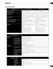
Appendix 08 8.3 Specifications Flat Panel TV Number of pixels Audio Amplifier Speaker Sound Effect On-Screen Languages Power Requirement Weight PRO-151FD (60") PRO-111FD (50") 1920 × 1080 pixels 1920 × 1080 pixels 18 W + 18 W (1 kHz, 10 %, 6 Ω) 18 W + 18 W (1 kHz, 10 %, 6 Ω) Woofer: 4.8 cm ...lbs) (including cables, speaker brackets and screws) Color Sensor: 0.1 kg (0.2 lbs) Total: 39.9 kg (88.0 lbs) Reception System Digital ATSC Digital TV system Circuit Type 8VSB/64QAM/256QAM Tuner VHF/UHF VHF Ch. 2 to 13 UHF Ch. 14 to 69 Tuner CATV Ch. 2 to 135 Audio format...
Appendix 08 8.3 Specifications Flat Panel TV Number of pixels Audio Amplifier Speaker Sound Effect On-Screen Languages Power Requirement Weight PRO-151FD (60") PRO-111FD (50") 1920 × 1080 pixels 1920 × 1080 pixels 18 W + 18 W (1 kHz, 10 %, 6 Ω) 18 W + 18 W (1 kHz, 10 %, 6 Ω) Woofer: 4.8 cm ...lbs) (including cables, speaker brackets and screws) Color Sensor: 0.1 kg (0.2 lbs) Total: 39.9 kg (88.0 lbs) Reception System Digital ATSC Digital TV system Circuit Type 8VSB/64QAM/256QAM Tuner VHF/UHF VHF Ch. 2 to 13 UHF Ch. 14 to 69 Tuner CATV Ch. 2 to 135 Audio format...
Owner's Manual
Page 146
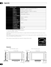
...: Design and specifications are subject to protect copyrighted digital contents that handles both video and audio using a single cable. Dimensions PRO-151FD (60" panel) 93 (3-21/32) 1677 (66-1/32) 93 (3-21/32) PRO-111FD (50" panel) 1445 (56-7/8) 723 (28-15/32) 788 (73818-1/32) 876 (34-1/2) 953 (37-17/32) 14 (9/16) 14...
...: Design and specifications are subject to protect copyrighted digital contents that handles both video and audio using a single cable. Dimensions PRO-151FD (60" panel) 93 (3-21/32) 1677 (66-1/32) 93 (3-21/32) PRO-111FD (50" panel) 1445 (56-7/8) 723 (28-15/32) 788 (73818-1/32) 876 (34-1/2) 953 (37-17/32) 14 (9/16) 14...


