Owner's Manual
Page 2
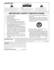
...OR BACK). REFER SERVICING TO QUALIFIED SERVICE PERSONNEL. A grounding type plug has two blades and a third grounding prong. When a cart is used, use caution when moving the cart/apparatus combination to avoid injury from tip-over. 13) Unplug this apparatus during lightning storms or when unused for ... produce heat. 9) Do not defeat the safety purpose of the obsolete outlet. 10) Protect the power cord from the apparatus. 11) Only use this product or cords associated with accessories sold with dry cloth. 7) Do not block any way, such as radiators, heat registers, stoves, ...
...OR BACK). REFER SERVICING TO QUALIFIED SERVICE PERSONNEL. A grounding type plug has two blades and a third grounding prong. When a cart is used, use caution when moving the cart/apparatus combination to avoid injury from tip-over. 13) Unplug this apparatus during lightning storms or when unused for ... produce heat. 9) Do not defeat the safety purpose of the obsolete outlet. 10) Protect the power cord from the apparatus. 11) Only use this product or cords associated with accessories sold with dry cloth. 7) Do not block any way, such as radiators, heat registers, stoves, ...
Owner's Manual
Page 3
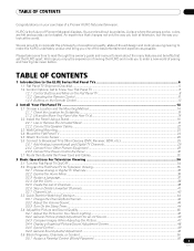
... the Panel Using a Stand ...16 2.2.1 Use or Remove the Included Stand ...16 2.2.2 Connect the Speaker Cables ...22 2.3 Wall/Ceiling Mounting...23 2.4 Mount the Flat Panel TV ...24 2.5 Attach the Color Sensor ...26 2.6 Connect to Broadcast TV & Other Devices (DVR, Receiver, BDR, etc 29 2.6.1 Add Analog (conventional) and Digital TV Channels 29 2.6.2 Connect Your Other Pioneer Equipment...
... the Panel Using a Stand ...16 2.2.1 Use or Remove the Included Stand ...16 2.2.2 Connect the Speaker Cables ...22 2.3 Wall/Ceiling Mounting...23 2.4 Mount the Flat Panel TV ...24 2.5 Attach the Color Sensor ...26 2.6 Connect to Broadcast TV & Other Devices (DVR, Receiver, BDR, etc 29 2.6.1 Add Analog (conventional) and Digital TV Channels 29 2.6.2 Connect Your Other Pioneer Equipment...
Owner's Manual
Page 4
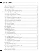
...TV 78 5.1 Program the Remote Control to Operate Other Equipment 78 5.1.1 Use the Learning Feature...78 5.1.2 Assign a Manufacturing Code to the Remote Control 79 5.1.3 Issue a Library Search for a Manufacturer Code 79 5.1.4 Clear Added Manufacturer Codes from the Remote Control 80 5.1.5 Control a Pioneer... Receiver ...80 5.1.6 Control a Cable (CBL) or Satellite (SAT) System 81 5.1.7 Control a Video Cassette Recorder (VCR) ...82 5.1.8 Control a DVD Player/DVR Recorder/BD Player 83 5.2 Use HDMI Inputs...84 5.2.1 Specify the HDMI Input Type...
...TV 78 5.1 Program the Remote Control to Operate Other Equipment 78 5.1.1 Use the Learning Feature...78 5.1.2 Assign a Manufacturing Code to the Remote Control 79 5.1.3 Issue a Library Search for a Manufacturer Code 79 5.1.4 Clear Added Manufacturer Codes from the Remote Control 80 5.1.5 Control a Pioneer... Receiver ...80 5.1.6 Control a Cable (CBL) or Satellite (SAT) System 81 5.1.7 Control a Video Cassette Recorder (VCR) ...82 5.1.8 Control a DVD Player/DVR Recorder/BD Player 83 5.2 Use HDMI Inputs...84 5.2.1 Specify the HDMI Input Type...
Owner's Manual
Page 5
... 5.4.3 Turn ON the Power With an HDMI Command ...91 5.4.4 Test the Power Control (On/Off)...92 5.5 Connect a Game Console or Camcorder ...92 5.6 Use the IR REPEATER OUT...92 5.7 Operate the Home Media Gallery ...93 5.7.1 Network Connections...94 5.7.2 Connect a USB Device...96 5.8 Run the Home Media Gallery...5.8.1 Show Your Movie Files on the Flat Panel TV ...101 5.8.2 Play Your Music Files on the Flat Panel TV ...103 5.8.3 Show Your Photo File on the Flat Panel TV ...104 5.9 Use the TOOLS Menu ...106 5.10 HMG Setup ...118 5.11 Other useful functions...119 5.12 Add Other Audio Equipment...121 ...
... 5.4.3 Turn ON the Power With an HDMI Command ...91 5.4.4 Test the Power Control (On/Off)...92 5.5 Connect a Game Console or Camcorder ...92 5.6 Use the IR REPEATER OUT...92 5.7 Operate the Home Media Gallery ...93 5.7.1 Network Connections...94 5.7.2 Connect a USB Device...96 5.8 Run the Home Media Gallery...5.8.1 Show Your Movie Files on the Flat Panel TV ...101 5.8.2 Play Your Music Files on the Flat Panel TV ...103 5.8.3 Show Your Photo File on the Flat Panel TV ...104 5.9 Use the TOOLS Menu ...106 5.10 HMG Setup ...118 5.11 Other useful functions...119 5.12 Add Other Audio Equipment...121 ...
Owner's Manual
Page 9
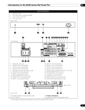
Introduction to both ELITE models. 9 En RC-232C terminal (for factory use) 10 - INPUT 4 terminals (Audio) 11 -INPUT 5 terminals (Audio) ... terminal (Audio) 22 -CONTROL OUT terminal 23 -DIGITAL OUT terminal (Optical) 24 -SPEAKERS (right/left) terminal (PRO-151FD) (lower bank) 25 26 27 28 25 -Speakers (R) terminal (speaker side) 26 -Color Sensor 27 -...Power On button 28 -Speakers (L) terminal (speaker side) Terminals on side and rear panels are common to the ELITE Series Flat Panel TVs 01 1 - AC In terminal (upper bank) Back of the Panel 1 5 (middle bank) 2 3 4 12 13 14 ...
Introduction to both ELITE models. 9 En RC-232C terminal (for factory use) 10 - INPUT 4 terminals (Audio) 11 -INPUT 5 terminals (Audio) ... terminal (Audio) 22 -CONTROL OUT terminal 23 -DIGITAL OUT terminal (Optical) 24 -SPEAKERS (right/left) terminal (PRO-151FD) (lower bank) 25 26 27 28 25 -Speakers (R) terminal (speaker side) 26 -Color Sensor 27 -...Power On button 28 -Speakers (L) terminal (speaker side) Terminals on side and rear panels are common to the ELITE Series Flat Panel TVs 01 1 - AC In terminal (upper bank) Back of the Panel 1 5 (middle bank) 2 3 4 12 13 14 ...
Owner's Manual
Page 10
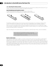
... of new batteries or cause chemical leaks in old batteries. Note: If the flat panel TV's remote control is not needed for the ELITE Series panels is weak batteries. When disposing of used batteries, please comply with the remote. If the panel responds then change the batteries. Weak... 10 En Also consider other IR signals can cause communication to fail or only operate sporadically. 01 Introduction to the ELITE Series Flat Panel TVs 1.2.2 Operating the Remote Control The remote control for an extended length of time, remove the batteries. If the remote control seems to be...
... of new batteries or cause chemical leaks in old batteries. Note: If the flat panel TV's remote control is not needed for the ELITE Series panels is weak batteries. When disposing of used batteries, please comply with the remote. If the panel responds then change the batteries. Weak... 10 En Also consider other IR signals can cause communication to fail or only operate sporadically. 01 Introduction to the ELITE Series Flat Panel TVs 1.2.2 Operating the Remote Control The remote control for an extended length of time, remove the batteries. If the remote control seems to be...
Owner's Manual
Page 11
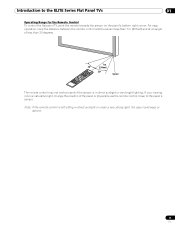
... the position of less than 7 m (23 feet) and at an angle of the panel or physically use the remote control closer to the ELITE Series Flat Panel TVs 01 Operating Range for the Remote Control To control the flat panel TV, point the remote towards the sensor on the panel's bottom right corner.
... the position of less than 7 m (23 feet) and at an angle of the panel or physically use the remote control closer to the ELITE Series Flat Panel TVs 01 Operating Range for the Remote Control To control the flat panel TV, point the remote towards the sensor on the panel's bottom right corner.
Owner's Manual
Page 12
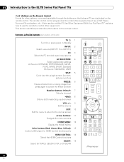
...13 14HDMI CTRL SOURCE STOP REC HMG RECEIVER VOL INPUT SELECT EDIT/LEARN 15 TV CBL DVD RCV SAT VCR DVR 12 En A later section entitled "5 Use Other Equipment With Your Flat Panel TV" explains how to use the remote to control other equipment such as an input source AV SELECTION: 4... HDMI Control functions SELECT: 15 Select for a few options, commands available through the buttons on the flat panel TV are duplicated on the remote control. The remote control can be programmed to right) TV : 1 Turn On or place panel in Standby INPUT: 2 Select a source (INPUT 1 thru INPUT 7) PC:...
...13 14HDMI CTRL SOURCE STOP REC HMG RECEIVER VOL INPUT SELECT EDIT/LEARN 15 TV CBL DVD RCV SAT VCR DVR 12 En A later section entitled "5 Use Other Equipment With Your Flat Panel TV" explains how to use the remote to control other equipment such as an input source AV SELECTION: 4... HDMI Control functions SELECT: 15 Select for a few options, commands available through the buttons on the flat panel TV are duplicated on the remote control. The remote control can be programmed to right) TV : 1 Turn On or place panel in Standby INPUT: 2 Select a source (INPUT 1 thru INPUT 7) PC:...
Owner's Manual
Page 13
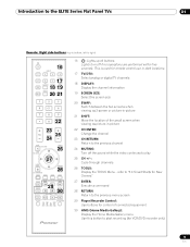
This is used for remote control use in dark locations. 17 TV/DTV: Select analog or digital TV channels 18 DISPLAY: Display the channel information 19 SCREEN SIZE: Select the screen size 20 SWAP: Switch between the two screens when viewing as 2-screen ... Media Gallery menu Use this button to start recording (for control of the small screen when viewing as picture-in-picture 22 CH ENTER: Change the channel 23 CH RETURN: Return to the previous channel 24 MUTING: Turn off the sound while the video continues to right) TV 16 INPUT 1 2 3 4 TV/DTV 17...
This is used for remote control use in dark locations. 17 TV/DTV: Select analog or digital TV channels 18 DISPLAY: Display the channel information 19 SCREEN SIZE: Select the screen size 20 SWAP: Switch between the two screens when viewing as 2-screen ... Media Gallery menu Use this button to start recording (for control of the small screen when viewing as picture-in-picture 22 CH ENTER: Change the channel 23 CH RETURN: Return to the previous channel 24 MUTING: Turn off the sound while the video continues to right) TV 16 INPUT 1 2 3 4 TV/DTV 17...
Owner's Manual
Page 14
... flat panel TV using a combination of the mounting method, anchor or secure your installer or dealer to purchase the appropriate bolt(s). 14 En Rear view (PRO-151FD) Mounting hole Mounting hole Side view Mounting surface Mounting bracket (or equivalent item) M8 screw 12 mm to 18 mm (0.5 inches to 0.7 inches) Rear view (PRO-111FD) W Mounting...
... flat panel TV using a combination of the mounting method, anchor or secure your installer or dealer to purchase the appropriate bolt(s). 14 En Rear view (PRO-151FD) Mounting hole Mounting hole Side view Mounting surface Mounting bracket (or equivalent item) M8 screw 12 mm to 18 mm (0.5 inches to 0.7 inches) Rear view (PRO-111FD) W Mounting...
Owner's Manual
Page 15
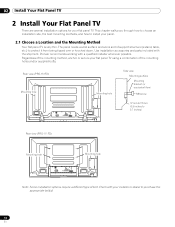
... lift and move the panel. The installation site should be handled with proper ventilation. Over 10 cm (3 15/16 inches) Over 50 cm (19 11/16 inches) The distance behind and above the panel changes depending on your dealer or professional installer for proper ventilation.... Use the handles attached to the rear of the flat panel TV to "7.2 Physical Location & Temperature Considerations" and "7.7 Safety Precautions." 2.1.2 Lift and/or Move Your Panel (the How ...
... lift and move the panel. The installation site should be handled with proper ventilation. Over 10 cm (3 15/16 inches) Over 50 cm (19 11/16 inches) The distance behind and above the panel changes depending on your dealer or professional installer for proper ventilation.... Use the handles attached to the rear of the flat panel TV to "7.2 Physical Location & Temperature Considerations" and "7.7 Safety Precautions." 2.1.2 Lift and/or Move Your Panel (the How ...
Owner's Manual
Page 16
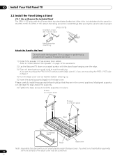
...is facing up. 5 ) Insert the stand supports (legs) into the base cover. 02 Install Your Flat Panel TV 2.2 Install the Panel Using a Stand 2.2.1 Use or Remove the Included Stand The PRO-111FD ships with Steps 4 and 5. En Attach the included stand to the panel for assistance. 2 ) Lay the flat...with the stand base hanging over so that they are mounting the PRO-151FD continue with the Pioneer table top stand (stand) attached. For PRO-111FD, attach the falling prevention metal fittings after placing the panel to stand upright. (PRO-111FD) Installation screws (M4 × 35 mm: black) Falling ...
...is facing up. 5 ) Insert the stand supports (legs) into the base cover. 02 Install Your Flat Panel TV 2.2 Install the Panel Using a Stand 2.2.1 Use or Remove the Included Stand The PRO-111FD ships with Steps 4 and 5. En Attach the included stand to the panel for assistance. 2 ) Lay the flat...with the stand base hanging over so that they are mounting the PRO-151FD continue with the Pioneer table top stand (stand) attached. For PRO-111FD, attach the falling prevention metal fittings after placing the panel to stand upright. (PRO-111FD) Installation screws (M4 × 35 mm: black) Falling ...
Owner's Manual
Page 17
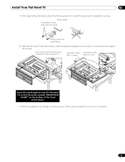
... 7 ) After assembling the stand, attach the falling prevention metal fittings using the installation screws. (PRO-151FD) Installation screws (M4 x 35 mm: black) Falling prevention metal fitting 8 ) With the flat panel TV still face down, insert the stand's supports into the flat panel TV so that the arrow marked "FRONT/FACE AVANT" on the bottom... then tighten the screws. Installation bolts (M6 x 20 mm) Installation bolts (M6 x 20 mm) Insert the stand supports into the bottom of the flat panel TV.
... 7 ) After assembling the stand, attach the falling prevention metal fittings using the installation screws. (PRO-151FD) Installation screws (M4 x 35 mm: black) Falling prevention metal fitting 8 ) With the flat panel TV still face down, insert the stand's supports into the flat panel TV so that the arrow marked "FRONT/FACE AVANT" on the bottom... then tighten the screws. Installation bolts (M6 x 20 mm) Installation bolts (M6 x 20 mm) Insert the stand supports into the bottom of the flat panel TV.
Owner's Manual
Page 19
...(left and right) to protect the equipment from scratches or other devices can damage the unit or cause a fire. • When using the supplied screws. (PRO-151FD) Screw holes Speaker bracket (For TOP-Right) Speaker bracket (For BOTTOM-Right) Screw holes Speaker bracket (For TOP-Right) Speaker... terminals (bottom) are facing you. 19 En Although other damage during mounting. Note: Use the foam packing materials to the top and bottom on the flat panel TV. Install Your Flat Panel TV 02 Attach/Detach the Speaker The flat panel TV's speaker delivers high-quality, clear sound.
...(left and right) to protect the equipment from scratches or other devices can damage the unit or cause a fire. • When using the supplied screws. (PRO-151FD) Screw holes Speaker bracket (For TOP-Right) Speaker bracket (For BOTTOM-Right) Screw holes Speaker bracket (For TOP-Right) Speaker... terminals (bottom) are facing you. 19 En Although other damage during mounting. Note: Use the foam packing materials to the top and bottom on the flat panel TV. Install Your Flat Panel TV 02 Attach/Detach the Speaker The flat panel TV's speaker delivers high-quality, clear sound.
Owner's Manual
Page 22
...) Speaker cable Speaker terminal Insertion in groove Speaker cable (PRO-111FD) Speaker terminal Insertion in the cable clamp then insert the clamp into the opening. 3 ) Allow a small percentage of the cable's bare wire to remain visible. Use the clamps as necessary (see page 33). tab 4 ) Release the tab to " 2.2.2 Connect the Speaker Cables... to the rear of the panel. Note: If the speaker needs to "2.7 Route then Bundle the Power Cord and Cables." 02 Install Your Flat Panel TV 8 ) Insert the cable in the groove on the rear of the flat panel...
...) Speaker cable Speaker terminal Insertion in groove Speaker cable (PRO-111FD) Speaker terminal Insertion in the cable clamp then insert the clamp into the opening. 3 ) Allow a small percentage of the cable's bare wire to remain visible. Use the clamps as necessary (see page 33). tab 4 ) Release the tab to " 2.2.2 Connect the Speaker Cables... to the rear of the panel. Note: If the speaker needs to "2.7 Route then Bundle the Power Cord and Cables." 02 Install Your Flat Panel TV 8 ) Insert the cable in the groove on the rear of the flat panel...
Owner's Manual
Page 24
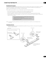
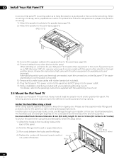
... another device. Anchor the Panel When Using a Stand When using the provided stand, follow the steps below to prepare the panel for mounting. 1 ) Attach the speaker brackets to the speaker (see page 19). 2 ) Attach the speaker to the panel (see page 21). (PRO-111FD) 3 ) Connect the speaker cables ...other equipment in the room. Another option is mounted. 5 ) Temporarily bundle loose cables with rubber bands (not included). 6 ) Plug the flat panel TV's power cord in to the panel but do NOT plug in this way, some way to the power outlet. 7 ) Follow installation directions provided with...
... another device. Anchor the Panel When Using a Stand When using the provided stand, follow the steps below to prepare the panel for mounting. 1 ) Attach the speaker brackets to the speaker (see page 19). 2 ) Attach the speaker to the panel (see page 21). (PRO-111FD) 3 ) Connect the speaker cables ...other equipment in the room. Another option is mounted. 5 ) Temporarily bundle loose cables with rubber bands (not included). 6 ) Plug the flat panel TV's power cord in to the panel but do NOT plug in this way, some way to the power outlet. 7 ) Follow installation directions provided with...
Owner's Manual
Page 25
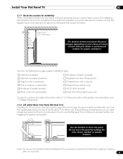
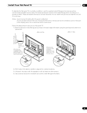
...as commercially available wood screws. Follow the steps below to secure your flat panel TV. 1 ) Mark locations for the cord. Install Your Flat Panel TV 02 To stabilize the flat panel TV on a table or platform, use bare wires for metal fittings and screws on the back edge of the display ...long. The wood screws are at the marked locations. 3 ) Lift panel into the ventilation port on the back of the table using the panel stand to determine placement. (PRO-151FD) (PRO-111FD) 8 mm to 15 mm (3/8 inch to the table. 25 En Notes: Avoid moving the table after the panel is introduced...
...as commercially available wood screws. Follow the steps below to secure your flat panel TV. 1 ) Mark locations for the cord. Install Your Flat Panel TV 02 To stabilize the flat panel TV on a table or platform, use bare wires for metal fittings and screws on the back edge of the display ...long. The wood screws are at the marked locations. 3 ) Lift panel into the ventilation port on the back of the table using the panel stand to determine placement. (PRO-151FD) (PRO-111FD) 8 mm to 15 mm (3/8 inch to the table. 25 En Notes: Avoid moving the table after the panel is introduced...
Owner's Manual
Page 26
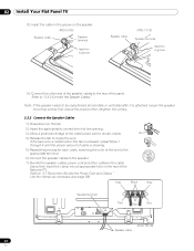
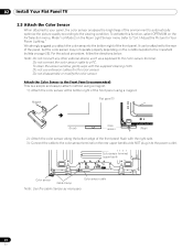
... (refer to "3.4.1 Adjust the Picture for the color sensor. Do not disassemble or modify the color sensor. Do not use extension cables for Your Room Lighting." Magnet Flat panel TV (Front) Color sensor (Rear) 2 ) Attach the color sensor along the bottom edge of the front panel flush with... the supplied cleaning cloth. Note: Do not connect any other external device, such as necessary. 26 En 02 Install Your Flat Panel TV 2.5 Attach the Color Sensor When attached to your panel, the color sensor analyses the brightness of the environment to automatically optimize the picture ...
... (refer to "3.4.1 Adjust the Picture for the color sensor. Do not disassemble or modify the color sensor. Do not use extension cables for Your Room Lighting." Magnet Flat panel TV (Front) Color sensor (Rear) 2 ) Attach the color sensor along the bottom edge of the front panel flush with... the supplied cleaning cloth. Note: Do not connect any other external device, such as necessary. 26 En 02 Install Your Flat Panel TV 2.5 Attach the Color Sensor When attached to your panel, the color sensor analyses the brightness of the environment to automatically optimize the picture ...

Owner's Manual
Page 27
...to a heat emitted from the panel. The color sensor may become hot due to the rear panel, the sensor window points upward. Use the removed screws again. (Bracket for PRO-111FD. 4 ) Fasten the screws. 5 ) Connect the cable to the color sensor terminal on the panel with or without sidemounted speakers. ...so as to the front panel. temperature environment, attach the color sensor to the bottom of the panel. When using the speaker brackets. Install Your Flat Panel TV 02 Attach the Color Sensor to the Rear Panel Methods of attaching the color sensor to the rear panel differ ...
...to a heat emitted from the panel. The color sensor may become hot due to the rear panel, the sensor window points upward. Use the removed screws again. (Bracket for PRO-111FD. 4 ) Fasten the screws. 5 ) Connect the cable to the color sensor terminal on the panel with or without sidemounted speakers. ...so as to the front panel. temperature environment, attach the color sensor to the bottom of the panel. When using the speaker brackets. Install Your Flat Panel TV 02 Attach the Color Sensor to the Rear Panel Methods of attaching the color sensor to the rear panel differ ...
Owner's Manual
Page 28
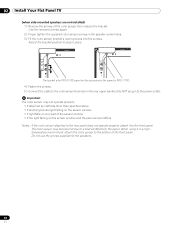
02 Install Your Flat Panel TV (when side-mounted speakers are not installed) 1 ) Remove the screws of the sensor window • if the light falling on the sensor window and the ... bracket's lower grooves into the screws. Important The color sensor may become hot due to the bottom of the front panel. Do not use the screws supplied for PRO-111FD. 4 ) Fasten the screws. 5 ) Connect the cable to the color sensor terminal on only part of the color sensor then replace the bracket. The...
02 Install Your Flat Panel TV (when side-mounted speakers are not installed) 1 ) Remove the screws of the sensor window • if the light falling on the sensor window and the ... bracket's lower grooves into the screws. Important The color sensor may become hot due to the bottom of the front panel. Do not use the screws supplied for PRO-111FD. 4 ) Fasten the screws. 5 ) Connect the cable to the color sensor terminal on only part of the color sensor then replace the bracket. The...


