Hardware Maintenance Manual
Page 3
...3 Handling devices that are sensitive to do first 29 Power system checkout 30 Checking the ac power adapter 30 Checking operational charging 31 Checking the battery pack 31 Chapter 4. General checkout . . . . . 29 What to electrostatic discharge 3 Grounding requirements 4 Safety notices (multilingual translations 4 ... panel, LCD cable, and hinges . . . . 75 2040 Antenna assembly and LCD rear cover . . . 77 Chapter 8. Lenovo B590 37 Specifications 37 Status indicators 38 Fn key combinations 39 Chapter 6. Notices 95 Electronic emissions notices 96 Trademarks 96 © Copyright...
...3 Handling devices that are sensitive to do first 29 Power system checkout 30 Checking the ac power adapter 30 Checking operational charging 31 Checking the battery pack 31 Chapter 4. General checkout . . . . . 29 What to electrostatic discharge 3 Grounding requirements 4 Safety notices (multilingual translations 4 ... panel, LCD cable, and hinges . . . . 75 2040 Antenna assembly and LCD rear cover . . . 77 Chapter 8. Lenovo B590 37 Specifications 37 Status indicators 38 Fn key combinations 39 Chapter 6. Notices 95 Electronic emissions notices 96 Trademarks 96 © Copyright...
Hardware Maintenance Manual
Page 9
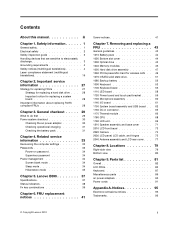
...equalizing the charge so that the machine, the part, the work mat, and the person handling the part are any obvious non-Lenovo alterations. Consider these conditions and the safety hazards they exceed the requirements noted here. Power off power. - Use a meter ... built, required safety items were installed to get medical aid. Check exterior covers for cracked or bulging batteries. 5. Check for damage (loose, broken, or sharp edges). 2. If any non-Lenovo alterations. 7. c. Chapter 1. Remove the cover. 6. A third-wire ground connector in identifying potentially ...
...equalizing the charge so that the machine, the part, the work mat, and the person handling the part are any obvious non-Lenovo alterations. Consider these conditions and the safety hazards they exceed the requirements noted here. Power off power. - Use a meter ... built, required safety items were installed to get medical aid. Check exterior covers for cracked or bulging batteries. 5. Check for damage (loose, broken, or sharp edges). 2. If any non-Lenovo alterations. 7. c. Chapter 1. Remove the cover. 6. A third-wire ground connector in identifying potentially ...
Hardware Maintenance Manual
Page 10
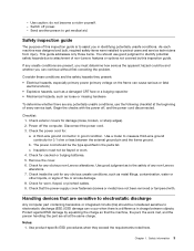
... Chinese DANGER DANGER 4 Hardware Maintenance Manual Grounding requirements Electrical grounding of a grounding system to eliminate static on these systems. - 2. When working on a double-insulated or battery-operated system, use coax or connector-outside shells on your body. • Prevent the part from touching your clothing. Use the round ground prong of...
... Chinese DANGER DANGER 4 Hardware Maintenance Manual Grounding requirements Electrical grounding of a grounding system to eliminate static on these systems. - 2. When working on a double-insulated or battery-operated system, use coax or connector-outside shells on your body. • Prevent the part from touching your clothing. Use the round ground prong of...
Hardware Maintenance Manual
Page 33
...from the Support Web site. • Do not try to replace either the processor board or the system board, and replacing one . © Copyright Lenovo 2012 27 After a system board is replaced, ensure that applies to the system board before you have both a processor board and a system board. ..., make sure that all machine types supported by product category 3. "Important notice for replacing FRUs Before replacing parts: Make sure that the battery is fully charged and an ac power adapter is installed to all software fixes, drivers, and BIOS downloads are available at http://www...
...from the Support Web site. • Do not try to replace either the processor board or the system board, and replacing one . © Copyright Lenovo 2012 27 After a system board is replaced, ensure that applies to the system board before you have both a processor board and a system board. ..., make sure that all machine types supported by product category 3. "Important notice for replacing FRUs Before replacing parts: Make sure that the battery is fully charged and an ac power adapter is installed to all software fixes, drivers, and BIOS downloads are available at http://www...
Hardware Maintenance Manual
Page 36
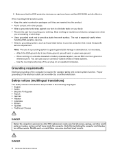
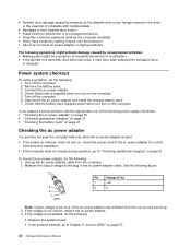
...• If the computer does not charge during operation, go to Chapter 5 "Lenovo B590" on page 37. 30 Hardware Maintenance Manual Remove the battery pack. 3. Disconnect the ac power adapter and install the charged battery pack. 7. Check that power is acceptable, do the following: 1. If you ... power supply checkouts: • "Checking the ac power adapter" on page 30 • "Checking operational charging" on page 31 • "Checking the battery pack" on the computer. Turn off the computer. 6. Unplug the ac power adapter cable from the one of the following figure: 3 2 1 (20V...
...• If the computer does not charge during operation, go to Chapter 5 "Lenovo B590" on page 37. 30 Hardware Maintenance Manual Remove the battery pack. 3. Disconnect the ac power adapter and install the charged battery pack. 7. Check that power is acceptable, do the following: 1. If you ... power supply checkouts: • "Checking the ac power adapter" on page 30 • "Checking operational charging" on page 31 • "Checking the battery pack" on the computer. Turn off the computer. 6. Unplug the ac power adapter cable from the one of the following figure: 3 2 1 (20V...
Hardware Maintenance Manual
Page 37
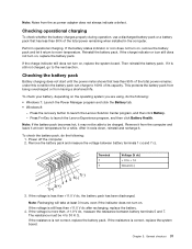
... 3. General checkout 31 After it cools down, reinstall and recharge it return to launch the Lenovo Experience program, and then click Battery Health. Power off the computer. 2. Checking the battery pack Battery charging does not start until the power meter shows that has less than +11.0 V dc...will take at room temperature for a while. To check your battery, depending on , remove the battery pack and let it . If the voltage is still not charged, go to launch the Lenovo Solution Center program, and then click Battery. - If the resistance is correct, replace the system board...
... 3. General checkout 31 After it cools down, reinstall and recharge it return to launch the Lenovo Experience program, and then click Battery Health. Power off the computer. 2. Checking the battery pack Battery charging does not start until the power meter shows that has less than +11.0 V dc...will take at room temperature for a while. To check your battery, depending on , remove the battery pack and let it . If the voltage is still not charged, go to launch the Lenovo Solution Center program, and then click Battery. - If the resistance is correct, replace the system board...
Hardware Maintenance Manual
Page 40
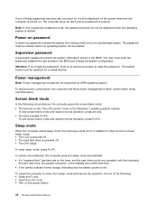
... any operation with the keyboard, the hard disk drive, the parallel connector, or the diskette drive within that time. • If the battery indicator blinks orange, indicating that the battery power is low. Sleep mode When the computer enters sleep mode, the following events occur in addition to what occurs in the...
... any operation with the keyboard, the hard disk drive, the parallel connector, or the diskette drive within that time. • If the battery indicator blinks orange, indicating that the battery power is low. Sleep mode When the computer enters sleep mode, the following events occur in addition to what occurs in the...
Hardware Maintenance Manual
Page 45
...cause drive errors. 4 Power and battery • Solid green: The battery charge level is between 80% and 100%, or the battery status indicator discharge level is between 20% and 100%. • Slow blinking green: The battery charge level is on a conventional ...keyboard. To resume normal operation, press the Fn key only. To disable the feature, press Fn+F2. Has the same function as the ScrLk key on , do not move the computer. Lenovo B590...
...cause drive errors. 4 Power and battery • Solid green: The battery charge level is between 80% and 100%, or the battery status indicator discharge level is between 20% and 100%. • Slow blinking green: The battery charge level is on a conventional ...keyboard. To resume normal operation, press the Fn key only. To disable the feature, press Fn+F2. Has the same function as the ScrLk key on , do not move the computer. Lenovo B590...
Hardware Maintenance Manual
Page 49
.... Before replacing any FRUs that a Service Provider install the CRU according to be found at any notes that all power cords from Lenovo at http://www.lenovo.com/UserManuals. Begin by , electrostatic discharge. When replacing a FRU, use in the drawing. 6. Before touching it, establish personal... as optional-service CRUs. Chapter 7. Follow the on how to replacement. 8. Such FRUs are available from electrical outlets, remove the battery pack, and then disconnect any FRU, turn it in place, reverse the removal procedure and follow any time upon request. If you...
.... Before replacing any FRUs that a Service Provider install the CRU according to be found at any notes that all power cords from Lenovo at http://www.lenovo.com/UserManuals. Begin by , electrostatic discharge. When replacing a FRU, use in the drawing. 6. Before touching it, establish personal... as optional-service CRUs. Chapter 7. Follow the on how to replacement. 8. Such FRUs are available from electrical outlets, remove the battery pack, and then disconnect any FRU, turn it in place, reverse the removal procedure and follow any time upon request. If you...

Hardware Maintenance Manual
Page 50
1010 Battery pack Removal steps of battery pack DANGER Use only the battery specified in the slot. Holding the manual battery latch in the unlocked position, remove the battery pack in the direction shown by the arrow 2 . 1 2 2 When installing: Install the battery pack in the parts list for your computer. Make sure that the battery latches are in the locked position. 1020 Bottom slot cover For access, remove this FRU: • "1010 Battery pack" on page 44 44 Hardware Maintenance Manual Unlock the spring-loaded battery latch 1 . Any other battery could ignite or explode.
1010 Battery pack Removal steps of battery pack DANGER Use only the battery specified in the slot. Holding the manual battery latch in the unlocked position, remove the battery pack in the direction shown by the arrow 2 . 1 2 2 When installing: Install the battery pack in the parts list for your computer. Make sure that the battery latches are in the locked position. 1020 Bottom slot cover For access, remove this FRU: • "1010 Battery pack" on page 44 44 Hardware Maintenance Manual Unlock the spring-loaded battery latch 1 . Any other battery could ignite or explode.

Hardware Maintenance Manual
Page 51
Removing and replacing a FRU 45 Removal steps of bottom slot cover Remove the screws 1 , and then remove the cover 2 . 1 1 2 2 Step 1 Screw (quantity) M2 × 3 mm, flat-head, nylon-coated (2) 1030 Optical drive For access, remove these FRUs in order: • "1010 Battery pack" on page 44 • "1020 Bottom slot cover" on page 44 Removal steps of optical drive Remove the screw 1 . 1 Color Black Torque 1.85 kgf-cm Step 1 Screw (quantity) M2 × 3 mm, flat-head, nylon-coated (1) Color Black Torque 1.85 kgf-cm Chapter 7.
Removing and replacing a FRU 45 Removal steps of bottom slot cover Remove the screws 1 , and then remove the cover 2 . 1 1 2 2 Step 1 Screw (quantity) M2 × 3 mm, flat-head, nylon-coated (2) 1030 Optical drive For access, remove these FRUs in order: • "1010 Battery pack" on page 44 • "1020 Bottom slot cover" on page 44 Removal steps of optical drive Remove the screw 1 . 1 Color Black Torque 1.85 kgf-cm Step 1 Screw (quantity) M2 × 3 mm, flat-head, nylon-coated (1) Color Black Torque 1.85 kgf-cm Chapter 7.
Hardware Maintenance Manual
Page 52
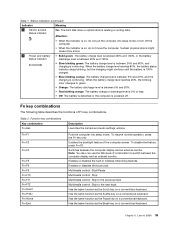
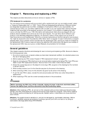
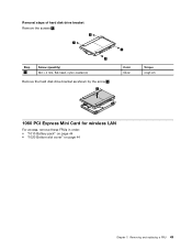
Then remove the optical drive. 3 2 Removal steps of optical drive bezel and optical drive bracket Remove the screws 1 and then remove the optical drive bracket. Insert a screwdriver into the screw hole 2 and push the optical drive in order: • "1010 Battery pack" on page 44 • "1020 Bottom slot cover" on page 44 46 Hardware Maintenance Manual 1 2 Color Black Torque 1.85 kgf-cm Step 1 Screw (quantity) M2 × 3 mm, flat-head, nylon-coated (2) 1040 Memory modules For access, remove these FRUs in the direction shown by the arrow 3 .
Then remove the optical drive. 3 2 Removal steps of optical drive bezel and optical drive bracket Remove the screws 1 and then remove the optical drive bracket. Insert a screwdriver into the screw hole 2 and push the optical drive in order: • "1010 Battery pack" on page 44 • "1020 Bottom slot cover" on page 44 46 Hardware Maintenance Manual 1 2 Color Black Torque 1.85 kgf-cm Step 1 Screw (quantity) M2 × 3 mm, flat-head, nylon-coated (2) 1040 Memory modules For access, remove these FRUs in the direction shown by the arrow 3 .
Hardware Maintenance Manual
Page 53
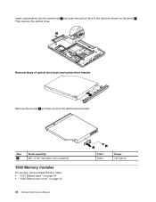
... is firmly installed in the slot and does not move easily. 1050 Hard disk drive assembly For access, remove these FRUs in order: • "1010 Battery pack" on page 44 • "1020 Bottom slot cover" on it snaps into the socket. The drive is in SLOT-1 ( b : upper slot). b a When installing: Insert...
... is firmly installed in the slot and does not move easily. 1050 Hard disk drive assembly For access, remove these FRUs in order: • "1010 Battery pack" on page 44 • "1020 Bottom slot cover" on it snaps into the socket. The drive is in SLOT-1 ( b : upper slot). b a When installing: Insert...
Hardware Maintenance Manual
Page 55
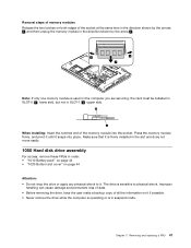
Removal steps of hard disk drive bracket Remove the screws 1 . 1 1 1 Step 1 Screw (quantity) M3 × 4 mm, flat-head, nylon-coated (4) Remove the hard disk drive bracket as shown by the arrow 2 . 2 1 Color Silver Torque 4 kgf-cm 1060 PCI Express Mini Card for wireless LAN For access, remove these FRUs in order: • "1010 Battery pack" on page 44 • "1020 Bottom slot cover" on page 44 Chapter 7. Removing and replacing a FRU 49
Removal steps of hard disk drive bracket Remove the screws 1 . 1 1 1 Step 1 Screw (quantity) M3 × 4 mm, flat-head, nylon-coated (4) Remove the hard disk drive bracket as shown by the arrow 2 . 2 1 Color Silver Torque 4 kgf-cm 1060 PCI Express Mini Card for wireless LAN For access, remove these FRUs in order: • "1010 Battery pack" on page 44 • "1020 Bottom slot cover" on page 44 Chapter 7. Removing and replacing a FRU 49

Hardware Maintenance Manual
Page 57
... if possible. • Never remove the drive while the computer is operating or is sensitive to physical shock. The drive is in order: • "1010 Battery pack" on page 44 • "1020 Bottom slot cover" on it .
... if possible. • Never remove the drive while the computer is operating or is sensitive to physical shock. The drive is in order: • "1010 Battery pack" on page 44 • "1020 Bottom slot cover" on it .

Hardware Maintenance Manual
Page 58
Remove the mSATA solid state drive 2 . 2 1080 Backup battery For access, remove these FRUs in order: • "1010 Battery pack" on page 44 • "1020 Bottom slot cover" on page 44 Removal steps of backup battery DANGER Use only the battery specified in the parts list for your computer. Any other battery could ignite or explode. 52 Hardware Maintenance Manual
Remove the mSATA solid state drive 2 . 2 1080 Backup battery For access, remove these FRUs in order: • "1010 Battery pack" on page 44 • "1020 Bottom slot cover" on page 44 Removal steps of backup battery DANGER Use only the battery specified in the parts list for your computer. Any other battery could ignite or explode. 52 Hardware Maintenance Manual
Hardware Maintenance Manual
Page 59
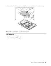
Removing and replacing a FRU 53 Insert a screwdriver into the backup battery hole and push the backup battery until the battery pops up. When installing: Ensure that the connector is attached firmly. 1090 Keyboard For access, remove these FRUs in order: • "1010 Battery pack" on page 44 • "1020 Bottom slot cover" on page 44 Chapter 7.
Removing and replacing a FRU 53 Insert a screwdriver into the backup battery hole and push the backup battery until the battery pops up. When installing: Ensure that the connector is attached firmly. 1090 Keyboard For access, remove these FRUs in order: • "1010 Battery pack" on page 44 • "1020 Bottom slot cover" on page 44 Chapter 7.
Hardware Maintenance Manual
Page 62
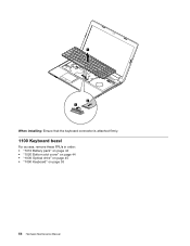
4 6 5 When installing: Ensure that the keyboard connector is attached firmly. 1100 Keyboard bezel For access, remove these FRUs in order: • "1010 Battery pack" on page 44 • "1020 Bottom slot cover" on page 44 • "1030 Optical drive" on page 45 • "1090 Keyboard" on page 53 56 Hardware Maintenance Manual
4 6 5 When installing: Ensure that the keyboard connector is attached firmly. 1100 Keyboard bezel For access, remove these FRUs in order: • "1010 Battery pack" on page 44 • "1020 Bottom slot cover" on page 44 • "1030 Optical drive" on page 45 • "1090 Keyboard" on page 53 56 Hardware Maintenance Manual
Hardware Maintenance Manual
Page 65
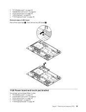
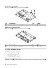
• "1010 Battery pack" on page 44 • "1020 Bottom slot cover" on page 44 • "1030 Optical drive" on page 45 • "1090 Keyboard" on page 53 &#..." on page 56 Chapter 7. Then remove the LED board 2 . 1 2 1120 Power board and touch pad bracket For access, remove these FRUs in order: • "1010 Battery pack" on page 44 • "1020 Bottom slot cover" on page 44 • "1030 Optical drive" on page 45 • "1090 Keyboard" on page 53...
• "1010 Battery pack" on page 44 • "1020 Bottom slot cover" on page 44 • "1030 Optical drive" on page 45 • "1090 Keyboard" on page 53 &#..." on page 56 Chapter 7. Then remove the LED board 2 . 1 2 1120 Power board and touch pad bracket For access, remove these FRUs in order: • "1010 Battery pack" on page 44 • "1020 Bottom slot cover" on page 44 • "1030 Optical drive" on page 45 • "1090 Keyboard" on page 53...
Hardware Maintenance Manual
Page 66
...) M2 × 3 mm, flat-head, nylon-coated (1) Removal steps of microphone assembly Detach the connector 1 , and then remove the microphone assembly in order: • "1010 Battery pack" on page 44 • "1020 Bottom slot cover" on page 44 • "1030 Optical drive" on page 45 • "1090 Keyboard" on page 53...
...) M2 × 3 mm, flat-head, nylon-coated (1) Removal steps of microphone assembly Detach the connector 1 , and then remove the microphone assembly in order: • "1010 Battery pack" on page 44 • "1020 Bottom slot cover" on page 44 • "1030 Optical drive" on page 45 • "1090 Keyboard" on page 53...


