Hardware Maintenance Manual
Page 3
... 43 1010 Battery pack 44 1020 Bottom slot cover 44 1030 Optical drive 45 1040 Memory modules 46 1050 Hard disk drive assembly 47 1060 PCI Express Mini Card for replacing a system board 28 Important information about replacing RoHS compliant FRUs 28 Chapter 3. Related service information 33 Recovering the computer settings 33 Passwords 33 Power-on password 34 Supervisor password 34 Power management 34 Screen blank mode 34 Sleep mode 34 Hibernation mode 35 Chapter 5. Locations 79 Right...
... 43 1010 Battery pack 44 1020 Bottom slot cover 44 1030 Optical drive 45 1040 Memory modules 46 1050 Hard disk drive assembly 47 1060 PCI Express Mini Card for replacing a system board 28 Important information about replacing RoHS compliant FRUs 28 Chapter 3. Related service information 33 Recovering the computer settings 33 Passwords 33 Power-on password 34 Supervisor password 34 Power management 34 Screen blank mode 34 Sleep mode 34 Hibernation mode 35 Chapter 5. Locations 79 Right...
Hardware Maintenance Manual
Page 8
... a machine: - When using testers, set the controls correctly and use the approved probe leads and accessories for safe operational condition. • Do not use this type of the units. • If an electrical accident occurs: 2 Hardware Maintenance Manual such touching can cause personal injury and machine damage. • Do not service the following rules when working on the machine, unplug the power cord. Ensure that...
... a machine: - When using testers, set the controls correctly and use the approved probe leads and accessories for safe operational condition. • Do not use this type of the units. • If an electrical accident occurs: 2 Hardware Maintenance Manual such touching can cause personal injury and machine damage. • Do not service the following rules when working on the machine, unplug the power cord. Ensure that...
Hardware Maintenance Manual
Page 33
... BIOS and device drivers are customer-installable. Strategy for replacing FRUs Before replacing parts: Make sure that the latest BIOS is installed to the system board before completing the service action. Click Download Drivers & Software. "Important notice for any FRUs listed in this manual: • "Strategy for replacing a hard disk drive" on the screen and install the necessary software. 4. After a system board is connected. • Do not turn off or put your search: • Search by product number...
... BIOS and device drivers are customer-installable. Strategy for replacing FRUs Before replacing parts: Make sure that the latest BIOS is installed to the system board before completing the service action. Click Download Drivers & Software. "Important notice for any FRUs listed in this manual: • "Strategy for replacing a hard disk drive" on the screen and install the necessary software. 4. After a system board is connected. • Do not turn off or put your search: • Search by product number...
Hardware Maintenance Manual
Page 35
..., clear the error log and run the test again. Consider replacing a FRU only when a problem recurs. What to use . When you replace FRUs, it : 1. Machine type, model number, and serial number 8. If you are not covered under warranty and some symptoms that might indicate that the system was subjected to it is a list of an optical drive © Copyright Lenovo 2012 29 Before checking problems with a hardware defect...
..., clear the error log and run the test again. Consider replacing a FRU only when a problem recurs. What to use . When you replace FRUs, it : 1. Machine type, model number, and serial number 8. If you are not covered under warranty and some symptoms that might indicate that the system was subjected to it is a list of an optical drive © Copyright Lenovo 2012 29 Before checking problems with a hardware defect...
Hardware Maintenance Manual
Page 36
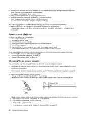
... bent diskette eject button • Fuses blown by attachment of a nonsupported device • Forgotten computer password (making the computer unusable) • Sticky keys caused by spilling a liquid onto the keyboard • Use of an incorrect ac power adapter on laptop products The following : 1. Power system checkout To verify a symptom, do the following: • Replace the system board. • If the problem persists, go to...
... bent diskette eject button • Fuses blown by attachment of a nonsupported device • Forgotten computer password (making the computer unusable) • Sticky keys caused by spilling a liquid onto the keyboard • Use of an incorrect ac power adapter on laptop products The following : 1. Power system checkout To verify a symptom, do the following: • Replace the system board. • If the problem persists, go to...
Hardware Maintenance Manual
Page 40
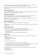
... Fn+F2. Sleep mode When the computer enters sleep mode, the following : • Press the Fn key. • Open the LCD cover. • Turn on the "Turn off . • The CPU stops. In certain circumstances, the computer goes into screen blank mode: • The time set on the power button. 34 Hardware Maintenance Manual Power-on password A power-on password protects the system from sleep mode and resume the operation, do any operation with the keyboard, the hard disk drive, the parallel...
... Fn+F2. Sleep mode When the computer enters sleep mode, the following : • Press the Fn key. • Open the LCD cover. • Turn on the "Turn off . • The CPU stops. In certain circumstances, the computer goes into screen blank mode: • The time set on the power button. 34 Hardware Maintenance Manual Power-on password A power-on password protects the system from sleep mode and resume the operation, do any operation with the keyboard, the hard disk drive, the parallel...
Hardware Maintenance Manual
Page 43
...) hard disk drive • mSATA solid state drive (on page 39 Specifications This topic lists the physical features for the Lenovo B590 models. then click Properties. • Windows 8: From the desktop, move the cursor to the top-right or bottom-right corner of your computer, click Start, right-click Computer; LCD: 1366-by -1536 • Camera Keyboard • 6-row Lenovo keyboard • Recovery button Interface • Combo audio jack (stereo...
...) hard disk drive • mSATA solid state drive (on page 39 Specifications This topic lists the physical features for the Lenovo B590 models. then click Properties. • Windows 8: From the desktop, move the cursor to the top-right or bottom-right corner of your computer, click Start, right-click Computer; LCD: 1366-by -1536 • Camera Keyboard • 6-row Lenovo keyboard • Recovery button Interface • Combo audio jack (stereo...
Hardware Maintenance Manual
Page 45
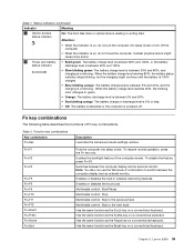
... sleep mode. When the battery charge level reaches 20%, the blinking color changes to green. • Orange: The battery discharge level is between 5% and 20%, and the charging is powered off the computer. • When the indicator is on a conventional keyboard. Has the same function as the ScrLk key on a conventional keyboard. Function key combinations Key combination Fn+Esc Description Launches the camera and audio settings window. Table 1. Multimedia control: Start/Pause Multimedia control...
... sleep mode. When the battery charge level reaches 20%, the blinking color changes to green. • Orange: The battery discharge level is between 5% and 20%, and the charging is powered off the computer. • When the indicator is on a conventional keyboard. Has the same function as the ScrLk key on a conventional keyboard. Function key combinations Key combination Fn+Esc Description Launches the camera and audio settings window. Table 1. Multimedia control: Start/Pause Multimedia control...
Hardware Maintenance Manual
Page 49
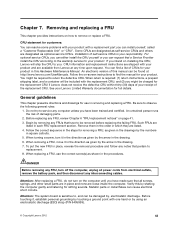
... and certified. Before touching it in the drawing. 7. CRU information and replacement instructions are listed. 4. Begin by the arrow in the direction as given by the numbers in the drawing. 6. Verify this Hardware Maintenance Manual. and (2) you have made sure that a Service Provider install the CRU according to the warranty service for your product in place, reverse the removal procedure and follow...
... and certified. Before touching it in the drawing. 7. CRU information and replacement instructions are listed. 4. Begin by the arrow in the direction as given by the numbers in the drawing. 6. Verify this Hardware Maintenance Manual. and (2) you have made sure that a Service Provider install the CRU according to the warranty service for your product in place, reverse the removal procedure and follow...
Hardware Maintenance Manual
Page 53
...; Before removing the drive, have the user make a backup copy of all the information on it if possible. • Never remove the drive while the computer is operating or is in order: • "1010 Battery pack" on page 44 • "1020 Bottom slot cover" on the computer you are servicing, the card must be installed in SLOT-0 ( a : lower slot), but not in SLOT-1 ( b : upper slot). Removal steps of memory modules Release the...
...; Before removing the drive, have the user make a backup copy of all the information on it if possible. • Never remove the drive while the computer is operating or is in order: • "1010 Battery pack" on page 44 • "1020 Bottom slot cover" on the computer you are servicing, the card must be installed in SLOT-0 ( a : lower slot), but not in SLOT-1 ( b : upper slot). Removal steps of memory modules Release the...
Hardware Maintenance Manual
Page 55
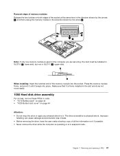
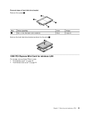
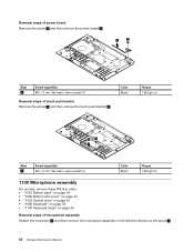
Removal steps of hard disk drive bracket Remove the screws 1 . 1 1 1 Step 1 Screw (quantity) M3 × 4 mm, flat-head, nylon-coated (4) Remove the hard disk drive bracket as shown by the arrow 2 . 2 1 Color Silver Torque 4 kgf-cm 1060 PCI Express Mini Card for wireless LAN For access, remove these FRUs in order: • "1010 Battery pack" on page 44 • "1020 Bottom slot cover" on page 44 Chapter 7. Removing and replacing a FRU 49
Removal steps of hard disk drive bracket Remove the screws 1 . 1 1 1 Step 1 Screw (quantity) M3 × 4 mm, flat-head, nylon-coated (4) Remove the hard disk drive bracket as shown by the arrow 2 . 2 1 Color Silver Torque 4 kgf-cm 1060 PCI Express Mini Card for wireless LAN For access, remove these FRUs in order: • "1010 Battery pack" on page 44 • "1020 Bottom slot cover" on page 44 Chapter 7. Removing and replacing a FRU 49
Hardware Maintenance Manual
Page 66
... Black Torque 1.85 kgf-cm 1130 Microphone assembly For access, remove these FRUs in order: • "1010 Battery pack" on page 44 • "1020 Bottom slot cover" on page 44 • "1030 Optical drive" on page 45 • "1090 Keyboard" on page 53 • "1100 Keyboard bezel" on page 56 Removal steps of touch pad bracket Remove the screw 1 and then remove the touch pad bracket 2 . Removal steps of power board Remove...
... Black Torque 1.85 kgf-cm 1130 Microphone assembly For access, remove these FRUs in order: • "1010 Battery pack" on page 44 • "1020 Bottom slot cover" on page 44 • "1030 Optical drive" on page 45 • "1090 Keyboard" on page 53 • "1100 Keyboard bezel" on page 56 Removal steps of touch pad bracket Remove the screw 1 and then remove the touch pad bracket 2 . Removal steps of power board Remove...
Hardware Maintenance Manual
Page 69
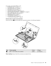
For access, remove these FRUs in order: • "1010 Battery pack" on page 44 • "1020 Bottom slot cover" on page 44 • "1030 Optical drive" on page 45 • "1040 Memory modules" on page 46 • "1050 Hard disk drive assembly" on page 47 • "1060 PCI Express Mini Card for wireless LAN" on page 49 • "1070 mSATA solid state drive" on page 51 •...
For access, remove these FRUs in order: • "1010 Battery pack" on page 44 • "1020 Bottom slot cover" on page 44 • "1030 Optical drive" on page 45 • "1040 Memory modules" on page 46 • "1050 Hard disk drive assembly" on page 47 • "1060 PCI Express Mini Card for wireless LAN" on page 49 • "1070 mSATA solid state drive" on page 51 •...
Hardware Maintenance Manual
Page 71
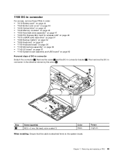
1160 DC-in connector For access, remove these FRUs in order: • "1010 Battery pack" on page 44 • "1020 Bottom slot cover" on page 44 • "1030 Optical drive" on page 45 • "1040 Memory modules" on page 46 • "1050 Hard disk drive assembly" on page 47 • "1060 PCI Express Mini Card for wireless LAN" on page 49 • "1070 mSATA solid state...
1160 DC-in connector For access, remove these FRUs in order: • "1010 Battery pack" on page 44 • "1020 Bottom slot cover" on page 44 • "1030 Optical drive" on page 45 • "1040 Memory modules" on page 46 • "1050 Hard disk drive assembly" on page 47 • "1060 PCI Express Mini Card for wireless LAN" on page 49 • "1070 mSATA solid state...
Hardware Maintenance Manual
Page 72
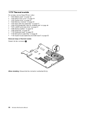
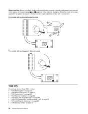
1170 Thermal module For access, remove these FRUs in order: • "1010 Battery pack" on page 44 • "1020 Bottom slot cover" on page 44 • "1030 Optical drive" on page 45 • "1040 Memory modules" on page 46 • "1050 Hard disk drive assembly" on page 47 • "1060 PCI Express Mini Card for wireless LAN" on page 49 • "1070 mSATA solid state drive" on page...
1170 Thermal module For access, remove these FRUs in order: • "1010 Battery pack" on page 44 • "1020 Bottom slot cover" on page 44 • "1030 Optical drive" on page 45 • "1040 Memory modules" on page 46 • "1050 Hard disk drive assembly" on page 47 • "1060 PCI Express Mini Card for wireless LAN" on page 49 • "1070 mSATA solid state drive" on page...
Hardware Maintenance Manual
Page 74
... Bottom slot cover" on page 44 • "1030 Optical drive" on page 45 • "1040 Memory modules" on page 46 • "1050 Hard disk drive assembly" on page 47 • "1060 PCI Express Mini Card for wireless LAN" on page 49 • "1070 mSATA solid state drive" on page 51 • "1080 Backup battery" on page 52 68 Hardware Maintenance Manual For models with a discrete thermal module a b For models with...
... Bottom slot cover" on page 44 • "1030 Optical drive" on page 45 • "1040 Memory modules" on page 46 • "1050 Hard disk drive assembly" on page 47 • "1060 PCI Express Mini Card for wireless LAN" on page 49 • "1070 mSATA solid state drive" on page 51 • "1080 Backup battery" on page 52 68 Hardware Maintenance Manual For models with a discrete thermal module a b For models with...
Hardware Maintenance Manual
Page 75
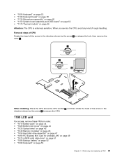
... the arrow b to secure the CPU. 1190 LCD unit For access, remove these FRUs in order: • "1010 Battery pack" on page 44 • "1020 Bottom slot cover" on page 44 • "1030 Optical drive" on page 45 • "1040 Memory modules" on page 46 • "1050 Hard disk drive assembly" on page 47 • "1060 PCI Express Mini Card for wireless LAN" on page 49 •...
... the arrow b to secure the CPU. 1190 LCD unit For access, remove these FRUs in order: • "1010 Battery pack" on page 44 • "1020 Bottom slot cover" on page 44 • "1030 Optical drive" on page 45 • "1040 Memory modules" on page 46 • "1050 Hard disk drive assembly" on page 47 • "1060 PCI Express Mini Card for wireless LAN" on page 49 •...
Hardware Maintenance Manual
Page 77
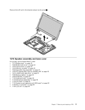
... 2 . 2 1210 Speaker assembly and base cover For access, remove these FRUs in order: • "1010 Battery pack" on page 44 • "1020 Bottom slot cover" on page 44 • "1030 Optical drive" on page 45 • "1040 Memory modules" on page 46 • "1050 Hard disk drive assembly" on page 47 • "1060 PCI Express Mini Card for wireless LAN" on page 49 • "1070 mSATA...
... 2 . 2 1210 Speaker assembly and base cover For access, remove these FRUs in order: • "1010 Battery pack" on page 44 • "1020 Bottom slot cover" on page 44 • "1030 Optical drive" on page 45 • "1040 Memory modules" on page 46 • "1050 Hard disk drive assembly" on page 47 • "1060 PCI Express Mini Card for wireless LAN" on page 49 • "1070 mSATA...
Hardware Maintenance Manual
Page 86
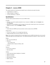
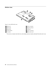
Bottom view 1 2 3 4 10 5 6 7 8 9 Figure 2. Lenovo B590 bottom view 1 Battery lock 2 Battery pack 3 Battery latch 4 Security keyhole 5 Fan louvers 6 Monitor connector 7 Ethernet connector 8 HDMI port 9 USB 3.0 connector 10 Bottom slot cover1 1 The memory modules, hard disk drive, and wireless cards are located underneath the bottom slot cover. 80 Hardware Maintenance Manual
Bottom view 1 2 3 4 10 5 6 7 8 9 Figure 2. Lenovo B590 bottom view 1 Battery lock 2 Battery pack 3 Battery latch 4 Security keyhole 5 Fan louvers 6 Monitor connector 7 Ethernet connector 8 HDMI port 9 USB 3.0 connector 10 Bottom slot cover1 1 The memory modules, hard disk drive, and wireless cards are located underneath the bottom slot cover. 80 Hardware Maintenance Manual
Hardware Maintenance Manual
Page 87
... depending on -screen instructions to the warranty service for your Lenovo Limited Warranty documentation for all types or models, unless otherwise specified. • A CRU is typically secured by no more than two screws. Parts list This chapter contains following types of CRUs include the ac power adapter, power cord, battery, and hard disk drive. If you can be required to you might include the memory module, wireless card, keyboard, and palm...
... depending on -screen instructions to the warranty service for your Lenovo Limited Warranty documentation for all types or models, unless otherwise specified. • A CRU is typically secured by no more than two screws. Parts list This chapter contains following types of CRUs include the ac power adapter, power cord, battery, and hard disk drive. If you can be required to you might include the memory module, wireless card, keyboard, and palm...


