Hardware Maintenance Manual
Page 3
... drive . . . 28 Important notice for wireless LAN . . 49 1070 mSATA solid state drive 51 1080 Backup battery 52 1090 Keyboard 53 1100 Keyboard bezel 56 1110 LED board 58 1120 Power board and touch pad bracket . . . . 59 1130 Microphone assembly 60 1140 I/O ... assembly 47 1060 PCI Express Mini Card for replacing a system board 28 Important information about replacing RoHS compliant FRUs 28 Chapter 3. Lenovo B590 37 Specifications 37 Status indicators 38 Fn key combinations 39 Chapter 6. Safety information 1 General safety 1 Electrical safety 2 Safety inspection ...
... drive . . . 28 Important notice for wireless LAN . . 49 1070 mSATA solid state drive 51 1080 Backup battery 52 1090 Keyboard 53 1100 Keyboard bezel 56 1110 LED board 58 1120 Power board and touch pad bracket . . . . 59 1130 Microphone assembly 60 1140 I/O ... assembly 47 1060 PCI Express Mini Card for replacing a system board 28 Important information about replacing RoHS compliant FRUs 28 Chapter 3. Lenovo B590 37 Specifications 37 Status indicators 38 Fn key combinations 39 Chapter 6. Safety information 1 General safety 1 Electrical safety 2 Safety inspection ...
Hardware Maintenance Manual
Page 36
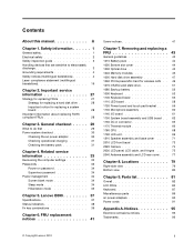
... Pin Voltage (V dc) 1 +20 2 0 Note: Output voltage of pin no.2 of the ac power adapter may have been subjected to Chapter 5 "Lenovo B590" on page 31 To check the ac power adapter, do the following: 1. Check that the battery pack supplies power when you turn on the computer...of a nonsupported device • Forgotten computer password (making the computer unusable) • Sticky keys caused by spilling a liquid onto the keyboard • Use of an incorrect ac power adapter on laptop products The following symptoms might indicate damage caused by nonwarranted activities: • ...
... Pin Voltage (V dc) 1 +20 2 0 Note: Output voltage of pin no.2 of the ac power adapter may have been subjected to Chapter 5 "Lenovo B590" on page 31 To check the ac power adapter, do the following: 1. Check that the battery pack supplies power when you turn on the computer...of a nonsupported device • Forgotten computer password (making the computer unusable) • Sticky keys caused by spilling a liquid onto the keyboard • Use of an incorrect ac power adapter on laptop products The following symptoms might indicate damage caused by nonwarranted activities: • ...
Hardware Maintenance Manual
Page 40
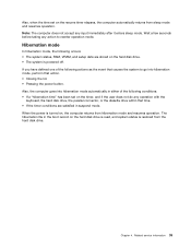
Power-on password A power-on password protects the system from sleep mode and resume the operation, do any operation with the keyboard, the hard disk drive, the parallel connector, or the diskette drive within that time. • If the battery indicator blinks orange, indicating that the battery ...
Power-on password A power-on password protects the system from sleep mode and resume the operation, do any operation with the keyboard, the hard disk drive, the parallel connector, or the diskette drive within that time. • If the battery indicator blinks orange, indicating that the battery ...
Hardware Maintenance Manual
Page 41
... resumes operation. Related service information 35 Also, when the time set on the timer, and if the user does not do any operation with the keyboard, the hard disk drive, the parallel connector, or the diskette drive within that action. • Closing the lid. • Pressing the power button. Also, the...
... resumes operation. Related service information 35 Also, when the time set on the timer, and if the user does not do any operation with the keyboard, the hard disk drive, the parallel connector, or the diskette drive within that action. • Closing the lid. • Pressing the power button. Also, the...
Hardware Maintenance Manual
Page 43
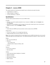
...: Maximum 2048-by -768 - Lenovo B590 This chapter presents the following product-specific service references and parts information: • "Specifications" on page 37 • "Status indicators" on page 38 • "Fn key combinations" on some models for "cache" function only. LCD: 1366-by -1536 • Camera Keyboard • 6-row Lenovo keyboard • Recovery button Interface...
...: Maximum 2048-by -768 - Lenovo B590 This chapter presents the following product-specific service references and parts information: • "Specifications" on page 37 • "Status indicators" on page 38 • "Fn key combinations" on some models for "cache" function only. LCD: 1366-by -1536 • Camera Keyboard • 6-row Lenovo keyboard • Recovery button Interface...
Hardware Maintenance Manual
Page 44
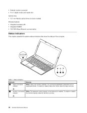
... Hardware Maintenance Manual You can type all alphabetic characters (A-Z) in -1 digital media card reader slot Optical drive • 12.7 mm Rambo optical drive (on the keyboard is enabled. • External monitor connector • 4-in uppercase directly. Status indicators Indicator 1 Caps Lock status indicator Meaning White: Caps Lock mode is enabled...
... Hardware Maintenance Manual You can type all alphabetic characters (A-Z) in -1 digital media card reader slot Optical drive • 12.7 mm Rambo optical drive (on the keyboard is enabled. • External monitor connector • 4-in uppercase directly. Status indicators Indicator 1 Caps Lock status indicator Meaning White: Caps Lock mode is enabled...
Hardware Maintenance Manual
Page 45
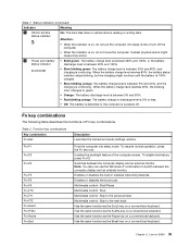
... combination Fn+Esc Description Launches the camera and audio settings window. Has the same function as the Pause key on a conventional keyboard. Chapter 5. Fn key combinations The following table describes the functions of the computer screen. Table 2. Enables or disables the built... to the next track Has the same function as the Break key on a conventional keyboard. Multimedia control: Start/Pause Multimedia control: Stop Multimedia control: Skip to the previous track Multimedia control: Skip to switch between the computer display and an external monitor. Lenovo B590 39
... combination Fn+Esc Description Launches the camera and audio settings window. Has the same function as the Pause key on a conventional keyboard. Chapter 5. Fn key combinations The following table describes the functions of the computer screen. Table 2. Enables or disables the built... to the next track Has the same function as the Break key on a conventional keyboard. Multimedia control: Start/Pause Multimedia control: Stop Multimedia control: Skip to the previous track Multimedia control: Skip to switch between the computer display and an external monitor. Lenovo B590 39
Hardware Maintenance Manual
Page 59
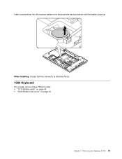
Removing and replacing a FRU 53 Insert a screwdriver into the backup battery hole and push the backup battery until the battery pops up. When installing: Ensure that the connector is attached firmly. 1090 Keyboard For access, remove these FRUs in order: • "1010 Battery pack" on page 44 • "1020 Bottom slot cover" on page 44 Chapter 7.
Removing and replacing a FRU 53 Insert a screwdriver into the backup battery hole and push the backup battery until the battery pops up. When installing: Ensure that the connector is attached firmly. 1090 Keyboard For access, remove these FRUs in order: • "1010 Battery pack" on page 44 • "1020 Bottom slot cover" on page 44 Chapter 7.
Hardware Maintenance Manual
Page 60
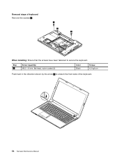
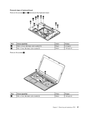
Step 1 Screw (quantity) M2.5 × 8 mm, flat-head, nylon-coated (3) Color Black Torque 4.0 kgf-cm Push hard in the direction shown by the arrow 2 to unlatch the front side of keyboard Remove the screws 1 . 1 1 1 When installing: Ensure that the screws have been fastened to secure the keyboard. Removal steps of the keyboard. 2 54 Hardware Maintenance Manual
Step 1 Screw (quantity) M2.5 × 8 mm, flat-head, nylon-coated (3) Color Black Torque 4.0 kgf-cm Push hard in the direction shown by the arrow 2 to unlatch the front side of keyboard Remove the screws 1 . 1 1 1 When installing: Ensure that the screws have been fastened to secure the keyboard. Removal steps of the keyboard. 2 54 Hardware Maintenance Manual
Hardware Maintenance Manual
Page 61
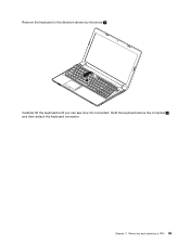
Chapter 7. Removing and replacing a FRU 55 Hold the keyboard above the computer 4 , and then detach the keyboard connector. Remove the keyboard in the direction shown by the arrow 3 . 3 Carefully lift the keyboard until you can see how it's connected.
Chapter 7. Removing and replacing a FRU 55 Hold the keyboard above the computer 4 , and then detach the keyboard connector. Remove the keyboard in the direction shown by the arrow 3 . 3 Carefully lift the keyboard until you can see how it's connected.
Hardware Maintenance Manual
Page 62
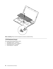
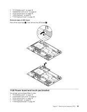
4 6 5 When installing: Ensure that the keyboard connector is attached firmly. 1100 Keyboard bezel For access, remove these FRUs in order: • "1010 Battery pack" on page 44 • "1020 Bottom slot cover" on page 44 • "1030 Optical drive" on page 45 • "1090 Keyboard" on page 53 56 Hardware Maintenance Manual
4 6 5 When installing: Ensure that the keyboard connector is attached firmly. 1100 Keyboard bezel For access, remove these FRUs in order: • "1010 Battery pack" on page 44 • "1020 Bottom slot cover" on page 44 • "1030 Optical drive" on page 45 • "1090 Keyboard" on page 53 56 Hardware Maintenance Manual
Hardware Maintenance Manual
Page 63
Removal steps of keyboard bezel Remove the screws 1 and 2 that secure the keyboard bezel. 2 2 2 11 1 1 1 1 1 1 1 1 Step 1 2 Screw (quantity) M2.5 × 8 mm, flat-head, nylon-coated (10) M2 × 3 mm, flat-head, nylon-coated (3) Remove the screws 3 . Removing and replacing a FRU 57 Color Black Black Torque 4.0 kgfcm 1.85 kgf-cm 3 3 3 Step 3 Screw (quantity) M2 × 5 mm, flat-head, nylon-coated (3) Color Black Torque 1.85 kgf-cm Chapter 7.
Removal steps of keyboard bezel Remove the screws 1 and 2 that secure the keyboard bezel. 2 2 2 11 1 1 1 1 1 1 1 1 Step 1 2 Screw (quantity) M2.5 × 8 mm, flat-head, nylon-coated (10) M2 × 3 mm, flat-head, nylon-coated (3) Remove the screws 3 . Removing and replacing a FRU 57 Color Black Black Torque 4.0 kgfcm 1.85 kgf-cm 3 3 3 Step 3 Screw (quantity) M2 × 5 mm, flat-head, nylon-coated (3) Color Black Torque 1.85 kgf-cm Chapter 7.

Hardware Maintenance Manual
Page 64
Remove the keyboard bezel. 10 10 10 11 10 10 10 1110 LED board For access, remove these FRUs in order: 58 Hardware Maintenance Manual 10 10 10 Detach the connectors. 5 4 8 9 6 7 When installing: Ensure that all the connectors are attached firmly.
Remove the keyboard bezel. 10 10 10 11 10 10 10 1110 LED board For access, remove these FRUs in order: 58 Hardware Maintenance Manual 10 10 10 Detach the connectors. 5 4 8 9 6 7 When installing: Ensure that all the connectors are attached firmly.
Hardware Maintenance Manual
Page 65
... Battery pack" on page 44 • "1020 Bottom slot cover" on page 44 • "1030 Optical drive" on page 45 • "1090 Keyboard" on page 53 • "1100 Keyboard bezel" on page 56 Removal steps of LED board Peel off the mylar tape 1 . • "1010 Battery pack" on page 44 • "1020... Bottom slot cover" on page 44 • "1030 Optical drive" on page 45 • "1090 Keyboard" on page 53 • "1100 Keyboard bezel" on page 56 Chapter 7. Removing and replacing a FRU 59
... Battery pack" on page 44 • "1020 Bottom slot cover" on page 44 • "1030 Optical drive" on page 45 • "1090 Keyboard" on page 53 • "1100 Keyboard bezel" on page 56 Removal steps of LED board Peel off the mylar tape 1 . • "1010 Battery pack" on page 44 • "1020... Bottom slot cover" on page 44 • "1030 Optical drive" on page 45 • "1090 Keyboard" on page 53 • "1100 Keyboard bezel" on page 56 Chapter 7. Removing and replacing a FRU 59
Hardware Maintenance Manual
Page 66
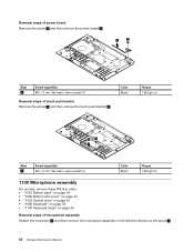
... order: • "1010 Battery pack" on page 44 • "1020 Bottom slot cover" on page 44 • "1030 Optical drive" on page 45 • "1090 Keyboard" on page 53 • "1100 Keyboard bezel" on page 56 Removal steps of touch pad bracket Remove the screw 1 and then remove the touch pad bracket 2 .
... order: • "1010 Battery pack" on page 44 • "1020 Bottom slot cover" on page 44 • "1030 Optical drive" on page 45 • "1090 Keyboard" on page 53 • "1100 Keyboard bezel" on page 56 Removal steps of touch pad bracket Remove the screw 1 and then remove the touch pad bracket 2 .
Hardware Maintenance Manual
Page 67
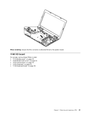
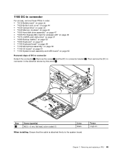
Removing and replacing a FRU 61 When installing: Ensure that the connector is attached firmly to the system board. 1140 I/O board For access, remove these FRUs in order: • "1010 Battery pack" on page 44 • "1020 Bottom slot cover" on page 44 • "1030 Optical drive" on page 45 • "1090 Keyboard" on page 53 • "1100 Keyboard bezel" on page 56 Chapter 7.
Removing and replacing a FRU 61 When installing: Ensure that the connector is attached firmly to the system board. 1140 I/O board For access, remove these FRUs in order: • "1010 Battery pack" on page 44 • "1020 Bottom slot cover" on page 44 • "1030 Optical drive" on page 45 • "1090 Keyboard" on page 53 • "1100 Keyboard bezel" on page 56 Chapter 7.
Hardware Maintenance Manual
Page 69
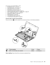
... LAN" on page 49 • "1070 mSATA solid state drive" on page 51 • "1080 Backup battery" on page 52 • "1090 Keyboard" on page 53 • "1100 Keyboard bezel" on page 56 • "1130 Microphone assembly" on page 60 Removal steps of system board assembly Remove the screws 1 , and then detach...
... LAN" on page 49 • "1070 mSATA solid state drive" on page 51 • "1080 Backup battery" on page 52 • "1090 Keyboard" on page 53 • "1100 Keyboard bezel" on page 56 • "1130 Microphone assembly" on page 60 Removal steps of system board assembly Remove the screws 1 , and then detach...
Hardware Maintenance Manual
Page 71
... wireless LAN" on page 49 • "1070 mSATA solid state drive" on page 51 • "1080 Backup battery" on page 52 • "1090 Keyboard" on page 53 • "1100 Keyboard bezel" on page 56 • "1130 Microphone assembly" on page 60 • "1140 I/O board" on page 61 • "1150 System board assembly...
... wireless LAN" on page 49 • "1070 mSATA solid state drive" on page 51 • "1080 Backup battery" on page 52 • "1090 Keyboard" on page 53 • "1100 Keyboard bezel" on page 56 • "1130 Microphone assembly" on page 60 • "1140 I/O board" on page 61 • "1150 System board assembly...
Hardware Maintenance Manual
Page 72
... LAN" on page 49 • "1070 mSATA solid state drive" on page 51 • "1080 Backup battery" on page 52 • "1090 Keyboard" on page 53 • "1100 Keyboard bezel" on page 56 • "1130 Microphone assembly" on page 60 • "1150 System board assembly and USB board" on page 62 Removal...
... LAN" on page 49 • "1070 mSATA solid state drive" on page 51 • "1080 Backup battery" on page 52 • "1090 Keyboard" on page 53 • "1100 Keyboard bezel" on page 56 • "1130 Microphone assembly" on page 60 • "1150 System board assembly and USB board" on page 62 Removal...
Hardware Maintenance Manual
Page 75
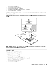
...; "1070 mSATA solid state drive" on page 51 • "1080 Backup battery" on page 52 • "1090 Keyboard" on page 66 Attention: The CPU is extremely sensitive. • "1090 Keyboard" on page 53 • "1100 Keyboard bezel" on page 56 • "1130 Microphone assembly" on page 60 • "1150 System board assembly and...
...; "1070 mSATA solid state drive" on page 51 • "1080 Backup battery" on page 52 • "1090 Keyboard" on page 66 Attention: The CPU is extremely sensitive. • "1090 Keyboard" on page 53 • "1100 Keyboard bezel" on page 56 • "1130 Microphone assembly" on page 60 • "1150 System board assembly and...


