Hardware Maintenance Manual
Page 3
...Important information about replacing RoHS compliant FRUs 28 Chapter 3. Notices 95 Electronic emissions notices 96 Trademarks 96 © Copyright Lenovo 2012 i Related service information 33 Recovering the computer settings 33 Passwords 33 Power-on password 34 Supervisor password 34 Power... bezel 73 2020 Camera 74 2030 LCD panel, LCD cable, and hinges . . . . 75 2040 Antenna assembly and LCD rear cover . . . 77 Chapter 8. FRU replacement notices 41 Screw notices 41 Chapter 7. Locations 79 Right-side view 79 Bottom view 80 Chapter 9. Lenovo B590 37 Specifications 37...
...Important information about replacing RoHS compliant FRUs 28 Chapter 3. Notices 95 Electronic emissions notices 96 Trademarks 96 © Copyright Lenovo 2012 i Related service information 33 Recovering the computer settings 33 Passwords 33 Power-on password 34 Supervisor password 34 Power... bezel 73 2020 Camera 74 2030 LCD panel, LCD cable, and hinges . . . . 75 2040 Antenna assembly and LCD rear cover . . . 77 Chapter 8. FRU replacement notices 41 Screw notices 41 Chapter 7. Locations 79 Right-side view 79 Bottom view 80 Chapter 9. Lenovo B590 37 Specifications 37...
Hardware Maintenance Manual
Page 43
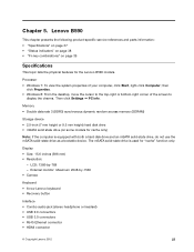
...cache" function only. Display • Size: 15.6 inches (396 mm) • Resolution: - External monitor: Maximum 2048-by -768 - Lenovo B590 This chapter presents the following product-specific service references and parts information: • "Specifications" on page 37 • "Status indicators" on ...; "Fn key combinations" on some models for cache only) Note: If the computer is used for the Lenovo B590 models. LCD: 1366-by -1536 • Camera Keyboard • 6-row Lenovo keyboard • Recovery button Interface • Combo audio jack (stereo headphone or headset) • USB ...
...cache" function only. Display • Size: 15.6 inches (396 mm) • Resolution: - External monitor: Maximum 2048-by -768 - Lenovo B590 This chapter presents the following product-specific service references and parts information: • "Specifications" on page 37 • "Status indicators" on ...; "Fn key combinations" on some models for cache only) Note: If the computer is used for the Lenovo B590 models. LCD: 1366-by -1536 • Camera Keyboard • 6-row Lenovo keyboard • Recovery button Interface • Combo audio jack (stereo headphone or headset) • USB ...
Hardware Maintenance Manual
Page 45
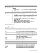
... 5% or less. • Off: The battery is detached or the computer is continuing. Function key combinations Key combination Fn+Esc Description Launches the camera and audio settings window. Chapter 5. Lenovo B590 39 When the battery charge level reaches 20%, the blinking color changes to green. • Orange: The battery discharge level is between...
... 5% or less. • Off: The battery is detached or the computer is continuing. Function key combinations Key combination Fn+Esc Description Launches the camera and audio settings window. Chapter 5. Lenovo B590 39 When the battery charge level reaches 20%, the blinking color changes to green. • Orange: The battery discharge level is between...

Hardware Maintenance Manual
Page 80
Then secure the bezel with the screws. 2020 Camera For access, remove these FRUs in the direction shown by the arrows 2 . 2 2 2 2 Torque 1.85 kgf-cm When installing: Make sure that all the latches are attached firmly. Removal steps of LCD front bezel Remove the screws 1 . 1 1 Step 1 Screw (quantity) M2 × 5 mm, flat-head, nylon-coated (2) Color Black Remove the LCD front bezel in order: • "1010 Battery pack" on page 44 • "1190 LCD unit" on page 69 • "2010 LCD front bezel" on page 73 74 Hardware Maintenance Manual
Then secure the bezel with the screws. 2020 Camera For access, remove these FRUs in the direction shown by the arrows 2 . 2 2 2 2 Torque 1.85 kgf-cm When installing: Make sure that all the latches are attached firmly. Removal steps of LCD front bezel Remove the screws 1 . 1 1 Step 1 Screw (quantity) M2 × 5 mm, flat-head, nylon-coated (2) Color Black Remove the LCD front bezel in order: • "1010 Battery pack" on page 44 • "1190 LCD unit" on page 69 • "2010 LCD front bezel" on page 73 74 Hardware Maintenance Manual

Hardware Maintenance Manual
Page 81
Removing and replacing a FRU 75 Removal steps of the LCD cover and adjust the placement to ensure that the connector is attached firmly. 2030 LCD panel, LCD cable, and hinges For access, remove these FRUs in the following illustration. Note: The camera is stuck on the top center of the LCD cover. 1 2 When installing: Stick the camera to the top center of camera Remove the camera from the LCD cover as shown in order: • "1010 Battery pack" on page 44 • "1190 LCD unit" on page 69 • "2010 LCD front bezel" on page 73 Chapter 7.
Removing and replacing a FRU 75 Removal steps of the LCD cover and adjust the placement to ensure that the connector is attached firmly. 2030 LCD panel, LCD cable, and hinges For access, remove these FRUs in the following illustration. Note: The camera is stuck on the top center of the LCD cover. 1 2 When installing: Stick the camera to the top center of camera Remove the camera from the LCD cover as shown in order: • "1010 Battery pack" on page 44 • "1190 LCD unit" on page 69 • "2010 LCD front bezel" on page 73 Chapter 7.

Hardware Maintenance Manual
Page 83
Removing and replacing a FRU 77 Then remove the hinges 2 . 1 2 1 1 2 Step 1 Screw (quantity) M2 × 3 mm, flat-head, nylon-coated (4) 2040 Antenna assembly and LCD rear cover For access, remove these FRUs in order: • "1010 Battery pack" on page 44 • "1190 LCD unit" on page 69 • "2010 LCD front bezel" on page 73 • "2020 Camera" on page 74 • "2030 LCD panel, LCD cable, and hinges" on page 75 1 Color Black Torque 1.85 kgf-cm Chapter 7. Removal steps of hinges Remove the screws 1 .
Removing and replacing a FRU 77 Then remove the hinges 2 . 1 2 1 1 2 Step 1 Screw (quantity) M2 × 3 mm, flat-head, nylon-coated (4) 2040 Antenna assembly and LCD rear cover For access, remove these FRUs in order: • "1010 Battery pack" on page 44 • "1190 LCD unit" on page 69 • "2010 LCD front bezel" on page 73 • "2020 Camera" on page 74 • "2030 LCD panel, LCD cable, and hinges" on page 75 1 Color Black Torque 1.85 kgf-cm Chapter 7. Removal steps of hinges Remove the screws 1 .
Hardware Maintenance Manual
Page 85
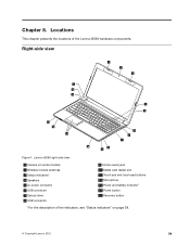
Locations This chapter presents the locations of the indicators, see "Status indicators" on page 38. © Copyright Lenovo 2012 79 Chapter 8. Lenovo B590 right-side view 1 Camera (on some models) 2 Wireless module antennas 3 Status indicators1 4 Speakers 5 ac power connector 6 USB connector 7 Optical drive 8 USB connector 9 Combo audio jack 10 ... and touch pad buttons 12 Microphone 13 Power and battery indicator1 14 Power button 15 Recovery button 1 For the description of the Lenovo B590 hardware components. Right-side view 2 1 2 4 15 14 3 4 13 12 11 5 6 7 10 8 9 Figure 1.
Locations This chapter presents the locations of the indicators, see "Status indicators" on page 38. © Copyright Lenovo 2012 79 Chapter 8. Lenovo B590 right-side view 1 Camera (on some models) 2 Wireless module antennas 3 Status indicators1 4 Speakers 5 ac power connector 6 USB connector 7 Optical drive 8 USB connector 9 Combo audio jack 10 ... and touch pad buttons 12 Microphone 13 Power and battery indicator1 14 Power button 15 Recovery button 1 For the description of the Lenovo B590 hardware components. Right-side view 2 1 2 4 15 14 3 4 13 12 11 5 6 7 10 8 9 Figure 1.

Hardware Maintenance Manual
Page 92
FRU 1 LB59A LCD Bezel WO/Camera Hole 1 LB59A LCD Bezel W/Camera Hole 2 LB58 Hinge L+R 3 LB58 Antenna R 4 LB58 Camera 0.3M 5 LB59A LCD Cover 6 LB58 Antenna L 7 Panel, 15.6 HD Wedge Glossy, SEC, LTN156AT24-L01 7 Panel, 15.6 HD Wedge Glossy, LGD, LP156WH4-TLN1 7 Panel, 15.6 HD ...
FRU 1 LB59A LCD Bezel WO/Camera Hole 1 LB59A LCD Bezel W/Camera Hole 2 LB58 Hinge L+R 3 LB58 Antenna R 4 LB58 Camera 0.3M 5 LB59A LCD Cover 6 LB58 Antenna L 7 Panel, 15.6 HD Wedge Glossy, SEC, LTN156AT24-L01 7 Panel, 15.6 HD Wedge Glossy, LGD, LP156WH4-TLN1 7 Panel, 15.6 HD ...

