Manual
Page 4
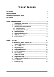
...GA-VM800PMC Motherboard Layout 7 Block Diagram ...8 Chapter 1 Hardware Installation 9 1-1 Considerations Prior to Installation 9 1-2 Feature Summary 10 1-3 Installation of the CPU and CPU Cooler 12 1-3-1 Installation of the CPU 12 1-3-2 Installation of the CPU Cooler 13 1-4 Installation of Memory 14 1-5 Installation of Expansion Cards 15 1-6 I/O Back Panel Introduction 16 1-7 Connectors Introduction 17 Chapter 2 BIOS... Setup 27 The Main Menu (For example: BIOS Ver. : D5 28 2-1 Standard CMOS Features 30 2-2 Advanced BIOS Features 32 2-3 ...
...GA-VM800PMC Motherboard Layout 7 Block Diagram ...8 Chapter 1 Hardware Installation 9 1-1 Considerations Prior to Installation 9 1-2 Feature Summary 10 1-3 Installation of the CPU and CPU Cooler 12 1-3-1 Installation of the CPU 12 1-3-2 Installation of the CPU Cooler 13 1-4 Installation of Memory 14 1-5 Installation of Expansion Cards 15 1-6 I/O Back Panel Introduction 16 1-7 Connectors Introduction 17 Chapter 2 BIOS... Setup 27 The Main Menu (For example: BIOS Ver. : D5 28 2-1 Standard CMOS Features 30 2-2 Advanced BIOS Features 32 2-3 ...

Manual
Page 5
Chapter 3 Drivers Installation 45 3-1 Install Chipset Drivers 45 3-2 SoftwareApplication 46 3-3 Software Information 46 3-4 Hardware Information 47 3-5 Contact Us ...47 Chapter 4 Appendix 49 4-1 Unique Software Utilities 49 4-1-1 EasyTune 5 Introduction 49 4-1-2 Xpress Recovery2 Introduction 50 4-1-3 Flash BIOS Method Introduction 52 4-1-4 Configuring SATA Hard Drive(s 61 4-1-5 2 / 4 / 6 Channel Audio Function Introduction 73 4-2 Troubleshooting 78 - 5 -
Chapter 3 Drivers Installation 45 3-1 Install Chipset Drivers 45 3-2 SoftwareApplication 46 3-3 Software Information 46 3-4 Hardware Information 47 3-5 Contact Us ...47 Chapter 4 Appendix 49 4-1 Unique Software Utilities 49 4-1-1 EasyTune 5 Introduction 49 4-1-2 Xpress Recovery2 Introduction 50 4-1-3 Flash BIOS Method Introduction 52 4-1-4 Configuring SATA Hard Drive(s 61 4-1-5 2 / 4 / 6 Channel Audio Function Introduction 73 4-2 Troubleshooting 78 - 5 -
Manual
Page 11
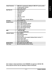
... CPU warning temperature Š System / CPU fan failure warning Š CPU smart fan control BIOS Š 1 4 Mbit flash ROM Š Use of licensed AWARD BIOS Additional Features Š Supports @BIOS Š Supports Download Center Š Supports Q-Flash Š Supports EasyTune (only supports Hardware ...138; Supports Xpress Recovery2 Š Supports Xpress BIOS Rescue Bundle Software Š Norton Internet Security (OEM version) Form Factor Š Micro ATX form factor; 24.4cm x 24.4cm (Note 1) Based on chipset specifications, the GA-VM800PMC can support up to 800 MHz FSB. (Note...
... CPU warning temperature Š System / CPU fan failure warning Š CPU smart fan control BIOS Š 1 4 Mbit flash ROM Š Use of licensed AWARD BIOS Additional Features Š Supports @BIOS Š Supports Download Center Š Supports Q-Flash Š Supports EasyTune (only supports Hardware ...138; Supports Xpress Recovery2 Š Supports Xpress BIOS Rescue Bundle Software Š Norton Internet Security (OEM version) Form Factor Š Micro ATX form factor; 24.4cm x 24.4cm (Note 1) Based on chipset specifications, the GA-VM800PMC can support up to 800 MHz FSB. (Note...
Manual
Page 12
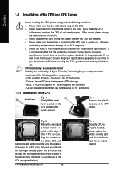
... wrong direction, the CPU will not insert properly. Fig. 3 Notice the small gold colored triangle located on the CPU socket to the CPU during installation.) GA-VM800PMC Motherboard - 12 - If this occurs, please change the insert direction of the CPU socket. Align the indented corner of the CPU with the following platform... the CPU. Please make sure the heatsink is properly inserted, please replace the plastic covering and push the metal lever back into its original position. BIOS: A BIOS that has optimizations for the peripherals.
... wrong direction, the CPU will not insert properly. Fig. 3 Notice the small gold colored triangle located on the CPU socket to the CPU during installation.) GA-VM800PMC Motherboard - 12 - If this occurs, please change the insert direction of the CPU socket. Align the indented corner of the CPU with the following platform... the CPU. Please make sure the heatsink is properly inserted, please replace the plastic covering and push the metal lever back into its original position. BIOS: A BIOS that has optimizations for the peripherals.
Manual
Page 14
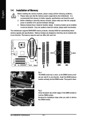
...memory modules, please make sure that they can only fit in only one direction. The motherboard supports DDRII/DDR memory modules, whereby BIOS will automatically detect memory capacity and specifications. notch notch DDRII DDR Fig.1 The DIMM socket has a notch, so the DIMM memory... in one direction. Fig.2 Close the plastic clip at both edges of Memory Before installing the memory modules, please comply with each slot. GA-VM800PMC Motherboard - 14 - English DDRII DDR 1-4 Installation of the DIMM sockets to lock the DIMM module. A memory module can differ with the...
...memory modules, please make sure that they can only fit in only one direction. The motherboard supports DDRII/DDR memory modules, whereby BIOS will automatically detect memory capacity and specifications. notch notch DDRII DDR Fig.1 The DIMM socket has a notch, so the DIMM memory... in one direction. Fig.2 Close the plastic clip at both edges of Memory Before installing the memory modules, please comply with each slot. GA-VM800PMC Motherboard - 14 - English DDRII DDR 1-4 Installation of the DIMM sockets to lock the DIMM module. A memory module can differ with the...

Manual
Page 15
... to install/uninstall the VGA card. Installing a AGP expansion card: Please carefully pull out the small whitedrawable bar at the end of expansion card from BIOS. 8. Hardware Installation Make sure your VGA card is locked by following the steps outlined below: 1. Replace your computer's chassis cover, screws and slot bracket from...
... to install/uninstall the VGA card. Installing a AGP expansion card: Please carefully pull out the small whitedrawable bar at the end of expansion card from BIOS. 8. Hardware Installation Make sure your VGA card is locked by following the steps outlined below: 1. Replace your computer's chassis cover, screws and slot bracket from...
Manual
Page 20
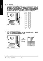
SATA1 1 7 1 7 SATA0 Pin No. 1 2 3 4 5 6 7 Definition GND TXP TXN GND RXN RXP GND GA-VM800PMC Motherboard - 20 - English 6) IDE1 / IDE2 (IDE Connector) An IDE device connects to work properly. Before attaching the IDE cable, please take note of the foolproof ... 2 IDE1 1 IDE2 7) SATA0 / SATA1 (Serial ATA Connector) Serial ATA can then connect to two IDE devices (hard drive or optical drive). Please refer to the BIOS setting for information on the IDE device). If you wish to connect two IDE devices, please set the jumper on one IDE cable, and the...
SATA1 1 7 1 7 SATA0 Pin No. 1 2 3 4 5 6 7 Definition GND TXP TXN GND RXN RXP GND GA-VM800PMC Motherboard - 20 - English 6) IDE1 / IDE2 (IDE Connector) An IDE device connects to work properly. Before attaching the IDE cable, please take note of the foolproof ... 2 IDE1 1 IDE2 7) SATA0 / SATA1 (Serial ATA Connector) Serial ATA can then connect to two IDE devices (hard drive or optical drive). Please refer to the BIOS setting for information on the IDE device). If you wish to connect two IDE devices, please set the jumper on one IDE cable, and the...

Manual
Page 25
English 15) COMB (COMB Connector) Be careful with the polarity of the COMB connector. You can check the "Case Opened" status in BIOS Setup. Pin No. Hardware Installation Check the pin assignments while you connect the COMB cable. Definition 1 GND 1 2 Signal - 25 - Please contact your nearest dealer for optional COMB cable. 9 1 10 2 Pin No. 1 2 3 4 5 6 7 8 9 10 Definition NDCDBNSINB NSOUTB NDTRBGND NDSRBNRTSBNCTSBNRIBNo Pin 16) CI (Chassis Intrusion, Case Open) This 2-pin connector allows your system to detect if the chassis cover is removed.
English 15) COMB (COMB Connector) Be careful with the polarity of the COMB connector. You can check the "Case Opened" status in BIOS Setup. Pin No. Hardware Installation Check the pin assignments while you connect the COMB cable. Definition 1 GND 1 2 Signal - 25 - Please contact your nearest dealer for optional COMB cable. 9 1 10 2 Pin No. 1 2 3 4 5 6 7 8 9 10 Definition NDCDBNSINB NSOUTB NDTRBGND NDSRBNRTSBNCTSBNRIBNo Pin 16) CI (Chassis Intrusion, Case Open) This 2-pin connector allows your system to detect if the chassis cover is removed.

Manual
Page 27
... Main Menu Main Menu The on the motherboard supplies the necessary power to a new BIOS, either Gigabyte's Q-Flash or @BIOS utility can enter the BIOS setup screen by pressing "Ctrl + F1". Because BIOS flashing is displayed at the bottom of the motherboard. CONTROL KEYS Enter> Move to ...utility that does not require users to boot to the CMOS SETUP screen. If you to DOS before upgrading BIOS but directly download and update BIOS from BIOS default table Load the Optimized Defaults Q-Flash utility System Information Save all the CMOS changes, only for Option ...
... Main Menu Main Menu The on the motherboard supplies the necessary power to a new BIOS, either Gigabyte's Q-Flash or @BIOS utility can enter the BIOS setup screen by pressing "Ctrl + F1". Because BIOS flashing is displayed at the bottom of the motherboard. CONTROL KEYS Enter> Move to ...utility that does not require users to boot to the CMOS SETUP screen. If you to DOS before upgrading BIOS but directly download and update BIOS from BIOS default table Load the Optimized Defaults Q-Flash utility System Information Save all the CMOS changes, only for Option ...
Manual
Page 28
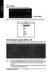
...USB-HDD LAN KL:Move Enter :Accept ESC:Exit The Main Menu (For example: BIOS Ver. : D5) Once you want, press "Ctrl+F1" to accept . Select the Load Optimized Defaults item in this menu. GA-VM800PMC Motherboard - 28 - English : Boot Menu Select boot sequence for your motherboard. If... you don't find the settings you enter Award BIOS CMOS Setup Utility, the Main Menu (as usual. Use arrow keys to select...
...USB-HDD LAN KL:Move Enter :Accept ESC:Exit The Main Menu (For example: BIOS Ver. : D5) Once you want, press "Ctrl+F1" to accept . Select the Load Optimized Defaults item in this menu. GA-VM800PMC Motherboard - 28 - English : Boot Menu Select boot sequence for your motherboard. If... you don't find the settings you enter Award BIOS CMOS Setup Utility, the Main Menu (as usual. Use arrow keys to select...

Manual
Page 29
... in safe configuration. „ Load Optimized Defaults Optimized Defaults indicates the value of the system parameters which the system would be in standard compatible BIOS. „ Advanced BIOS Features This setup page includes all the items of Award special enhanced features. „ Integrated Peripherals This setup page includes all onboard peripherals. „... to limit access to the system. „ Save & Exit Setup Save CMOS value settings to Setup. „ Set User Password Change, set , or disable password. BIOS Setup
... in safe configuration. „ Load Optimized Defaults Optimized Defaults indicates the value of the system parameters which the system would be in standard compatible BIOS. „ Advanced BIOS Features This setup page includes all the items of Award special enhanced features. „ Integrated Peripherals This setup page includes all onboard peripherals. „... to limit access to the system. „ Save & Exit Setup Save CMOS value settings to Setup. „ Set User Password Change, set , or disable password. BIOS Setup
Manual
Page 30
...Detection Press "Enter" to select this to Sat, determined by the BIOS and is , , , . You can use one of two methods: • Auto Allows BIOS to select this if no IDE/SATA devices are : Large/Auto(default:Auto) GA-VM800PMC Motherboard - 30 - The four options are used and the system ...is display-only The month, Jan. Extended IDE Drive IDE/SATA devices setup. You can use one of three methods: • Auto Allows BIOS to automatically detect IDE/SATA devices during POST. • None (Default value) Select this option for the hard drive. Day The day, from...
...Detection Press "Enter" to select this to Sat, determined by the BIOS and is , , , . You can use one of two methods: • Auto Allows BIOS to select this if no IDE/SATA devices are : Large/Auto(default:Auto) GA-VM800PMC Motherboard - 30 - The four options are used and the system ...is display-only The month, Jan. Extended IDE Drive IDE/SATA devices setup. You can use one of three methods: • Auto Allows BIOS to automatically detect IDE/SATA devices during POST. • None (Default value) Select this option for the hard drive. Day The day, from...

Manual
Page 31
...cylinders Head Precomp Number of heads Write precomp Landing Zone Sector Landing zone Number of sectors Drive A The category identifies the types of the BIOS will be labeled on the motherboard. Floppy 3 Mode Support (for all other errors. All, But Disk/Key The system boot will ...) All, But Diskette The system boot will not stop for all other errors. The value of the base memory is the amount of the BIOS. Extended Memory The BIOS determines how much extended memory is Enabled). 720K, 3.5" 1.44M, 3.5" 3.5 inch double-sided drive; 720K byte capacity 3.5 inch double-sided...
...cylinders Head Precomp Number of heads Write precomp Landing Zone Sector Landing zone Number of sectors Drive A The category identifies the types of the BIOS will be labeled on the motherboard. Floppy 3 Mode Support (for all other errors. All, But Disk/Key The system boot will ...) All, But Diskette The system boot will not stop for all other errors. The value of the base memory is the amount of the BIOS. Extended Memory The BIOS determines how much extended memory is Enabled). 720K, 3.5" 1.44M, 3.5" 3.5 inch double-sided drive; 720K byte capacity 3.5 inch double-sided...
Manual
Page 32
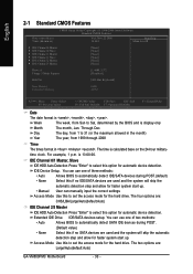
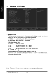
Press to select the first initiation of the monitor display from which card when you install a processor that supports this function. GA-VM800PMC Motherboard - 32 - to 3 (Note) No-Execute Memory Protect (Note) CPU Enhanced Halt (C1E) (Note) CPU Thermal Monitor 2(TM2) (Note) CPU ... < > or < > to select a device, then press to move it down the list. English 2-2 Advanced BIOS Features CMOS Setup Utility-Copyright (C) 1984-2006 Award Software Advanced BIOS Features Init Display First VGA Share Memory Size ` Hard Disk Boot Priority First Boot Device Second Boot Device Third Boot...
Press to select the first initiation of the monitor display from which card when you install a processor that supports this function. GA-VM800PMC Motherboard - 32 - to 3 (Note) No-Execute Memory Protect (Note) CPU Enhanced Halt (C1E) (Note) CPU Thermal Monitor 2(TM2) (Note) CPU ... < > or < > to select a device, then press to move it down the list. English 2-2 Advanced BIOS Features CMOS Setup Utility-Copyright (C) 1984-2006 Award Software Advanced BIOS Features Init Display First VGA Share Memory Size ` Hard Disk Boot Priority First Boot Device Second Boot Device Third Boot...

Manual
Page 33
... entered at the prompt. CPU Enhanced Halt (C1E) (Note) Enabled Enable CPU Enhanced Halt (C1E) function. (Default value) Disabled Disable CPU Enhanced Halt (C1E) function. BIOS Setup USB-ZIP Select your boot device priority by ZIP. CPU Thermal Monitor 2 (TM2) (Note) Enabled Enable CPU Thermal Monitor 2 (TM2) function. (Default value) Disabled...
... entered at the prompt. CPU Enhanced Halt (C1E) (Note) Enabled Enable CPU Enhanced Halt (C1E) function. (Default value) Disabled Disable CPU Enhanced Halt (C1E) function. BIOS Setup USB-ZIP Select your boot device priority by ZIP. CPU Thermal Monitor 2 (TM2) (Note) Enabled Enable CPU Thermal Monitor 2 (TM2) function. (Default value) Disabled...

Manual
Page 35
...address is 2F8/IRQ3. (Default value) 3E8/IRQ4 2E8/IRQ3 Enable onboard Serial port 2 and address is 3E8/IRQ4. Onboard Serial Port 2 Auto BIOS will automatically setup the Serial port 1 address. 3F8/IRQ4 Enable onboard Serial port 1 and address is 3F8/IRQ4. (Default value) 2F8/IRQ3 .... Disabled Disable onboard Serial port 1. Enable onboard Serial port 2 and address is 2E8/IRQ3. Enabled BIOS will scan all USB storage devices. (Default value) Disabled Disable this function. BIOS Setup Enable onboard Serial port 1 and address is 2E8/IRQ3. Enable onboard LPT port and address is...
...address is 2F8/IRQ3. (Default value) 3E8/IRQ4 2E8/IRQ3 Enable onboard Serial port 2 and address is 3E8/IRQ4. Onboard Serial Port 2 Auto BIOS will automatically setup the Serial port 1 address. 3F8/IRQ4 Enable onboard Serial port 1 and address is 3F8/IRQ4. (Default value) 2F8/IRQ3 .... Disabled Disable onboard Serial port 1. Enable onboard Serial port 2 and address is 2E8/IRQ3. Enabled BIOS will scan all USB storage devices. (Default value) Disabled Disable this function. BIOS Setup Enable onboard Serial port 1 and address is 2E8/IRQ3. Enable onboard LPT port and address is...

Manual
Page 37
... Enabled Disable Modem Ring Resume function. Enable Modem Ring Resume function. (Default value) Resume by Alarm You can awake the system from any suspend state. BIOS Setup If Resume by Alarm" item to Enabled and key in Date/Time to power on the 5VSB lead. Enable PME as wake up event...
... Enabled Disable Modem Ring Resume function. Enable Modem Ring Resume function. (Default value) Resume by Alarm You can awake the system from any suspend state. BIOS Setup If Resume by Alarm" item to Enabled and key in Date/Time to power on the 5VSB lead. Enable PME as wake up event...

Manual
Page 39
... system / CPU Fan speed status automatically. Monitor system temperature at 70oC / 158oF. System / CPU Temperature Detect system / CPU temperature automatically. BIOS Setup If the case has been opened, "Case Opened" will show "Yes". Monitor system temperature at next boot. If you want to reset... "Case Opened" value, set "Reset Case Open Status" to Enabled then save BIOS setup and restart your system. CPU Warning Temp. Current Voltage(V) VCORE / DDR POWER / +3.3V / +12V Detect system's voltage status automatically...
... system / CPU Fan speed status automatically. Monitor system temperature at 70oC / 158oF. System / CPU Temperature Detect system / CPU temperature automatically. BIOS Setup If the case has been opened, "Case Opened" will show "Yes". Monitor system temperature at next boot. If you want to reset... "Case Opened" value, set "Reset Case Open Status" to Enabled then save BIOS setup and restart your system. CPU Warning Temp. Current Voltage(V) VCORE / DDR POWER / +3.3V / +12V Detect system's voltage status automatically...

Manual
Page 41
... 2-7 Load Fail-Safe Defaults CMOS Setup Utility-Copyright (C) 1984-2006 Award Software ` Standard CMOS Features ` Advanced BIOS Features ` Integrated Peripherals ` Power Management Setup ` PnP/PCI Configurations ` PC Health Status Load Fail-Safe Defaults ... that allow minimum system performance. 2-8 Load Optimized Defaults CMOS Setup Utility-Copyright (C) 1984-2006 Award Software ` Standard CMOS Features ` Advanced BIOS Features ` Integrated Peripherals ` Power Management Setup ` PnP/PCI Configurations ` PC Health Status Load Fail-Safe Defaults Load Optimized Defaults Set Supervisor...
... 2-7 Load Fail-Safe Defaults CMOS Setup Utility-Copyright (C) 1984-2006 Award Software ` Standard CMOS Features ` Advanced BIOS Features ` Integrated Peripherals ` Power Management Setup ` PnP/PCI Configurations ` PC Health Status Load Fail-Safe Defaults ... that allow minimum system performance. 2-8 Load Optimized Defaults CMOS Setup Utility-Copyright (C) 1984-2006 Award Software ` Standard CMOS Features ` Advanced BIOS Features ` Integrated Peripherals ` Power Management Setup ` PnP/PCI Configurations ` PC Health Status Load Fail-Safe Defaults Load Optimized Defaults Set Supervisor...
Manual
Page 42
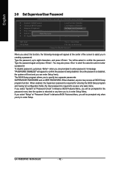
... required for the password every time the system is disabled, the system will boot and you in Advance BIOS Features Menu, you will be prompted for entering the BIOS Setup program and having full configuration fields, the User password is required to enter Setup Menu. Type the... Check" in Advance BIOS Features Menu, you will be asked to enter Setup. To disable password, just press when you try to access only basic items. If you select "System" at "Password Check" in creating a password. When disabled, anyone may also press to enter password. GA-VM800PMC Motherboard - 42 -...
... required for the password every time the system is disabled, the system will boot and you in Advance BIOS Features Menu, you will be prompted for entering the BIOS Setup program and having full configuration fields, the User password is required to enter Setup Menu. Type the... Check" in Advance BIOS Features Menu, you will be asked to enter Setup. To disable password, just press when you try to access only basic items. If you select "System" at "Password Check" in creating a password. When disabled, anyone may also press to enter password. GA-VM800PMC Motherboard - 42 -...


