
Manual
Page 5
Chapter 3 Drivers Installation 45 3-1 Install Chipset Drivers 45 3-2 SoftwareApplication 46 3-3 Software Information 46 3-4 Hardware Information 47 3-5 Contact Us ...47 Chapter 4 Appendix 49 4-1 Unique Software Utilities 49 4-1-1 EasyTune 5 Introduction 49 4-1-2 Xpress Recovery2 Introduction 50 4-1-3 Flash BIOS Method Introduction 52 4-1-4 Configuring SATA Hard Drive(s 61 4-1-5 2 / 4 / 6 Channel Audio Function Introduction 73 4-2 Troubleshooting 78 - 5 -
Chapter 3 Drivers Installation 45 3-1 Install Chipset Drivers 45 3-2 SoftwareApplication 46 3-3 Software Information 46 3-4 Hardware Information 47 3-5 Contact Us ...47 Chapter 4 Appendix 49 4-1 Unique Software Utilities 49 4-1-1 EasyTune 5 Introduction 49 4-1-2 Xpress Recovery2 Introduction 50 4-1-3 Flash BIOS Method Introduction 52 4-1-4 Configuring SATA Hard Drive(s 61 4-1-5 2 / 4 / 6 Channel Audio Function Introduction 73 4-2 Troubleshooting 78 - 5 -

Manual
Page 6
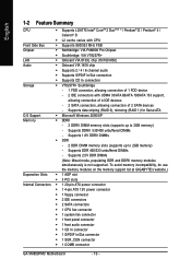
Item Checklist IDE Cable x 1, FDD Cable x 1 SATA Cable x 1 I/O Shield * The items listed above are for reference only, and are subject to change without notice. Optional Accessories Š 2 Ports USB 2.0 Cable (Part Number: 12CR1-1UB030-51/R) Š 4 Ports USB 2.0 Cable (Part Number: 12CR1-1UB030-21/R) Š 6-Channel Audio Combo Kit (Part Number: 12CR1-1SPAUD-12) Š S/PDIF In and Out Cable (Part Number: 12CR1-1SPINO-11/R) Š COM Port Cable (Part Number: 12CF1-1CM001-31/12CF1-1CM001-12R) - 6 -
Item Checklist IDE Cable x 1, FDD Cable x 1 SATA Cable x 1 I/O Shield * The items listed above are for reference only, and are subject to change without notice. Optional Accessories Š 2 Ports USB 2.0 Cable (Part Number: 12CR1-1UB030-51/R) Š 4 Ports USB 2.0 Cable (Part Number: 12CR1-1UB030-21/R) Š 6-Channel Audio Combo Kit (Part Number: 12CR1-1SPAUD-12) Š S/PDIF In and Out Cable (Part Number: 12CR1-1SPINO-11/R) Š COM Port Cable (Part Number: 12CF1-1CM001-31/12CF1-1CM001-12R) - 6 -
Manual
Page 10
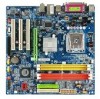
...2 DDRII DIMM memory slots (supports up to 2GB memory) - To avoid memory incompatibility, do use the memory modules on the memory support list at GIGABYTE's website.) Expanstion Slots Š 1 AGP slot Š 3 PCI slots Internal Connectors Š 1 20-pin ATX power connector Š 1 ... Š 2 SATA connectors Š 1 CPU fan connector Š 1 system fan connector Š 1 front panel connector Š 1 front audio connector Š 1 CD In connector Š 1 S/PDIF In/Out connector Š 1 SUR_CEN connector Š 1 COMB connector GA-VM800PMC Motherboard - 10 -
...2 DDRII DIMM memory slots (supports up to 2GB memory) - To avoid memory incompatibility, do use the memory modules on the memory support list at GIGABYTE's website.) Expanstion Slots Š 1 AGP slot Š 3 PCI slots Internal Connectors Š 1 20-pin ATX power connector Š 1 ... Š 2 SATA connectors Š 1 CPU fan connector Š 1 system fan connector Š 1 front panel connector Š 1 front audio connector Š 1 CD In connector Š 1 S/PDIF In/Out connector Š 1 SUR_CEN connector Š 1 COMB connector GA-VM800PMC Motherboard - 10 -
Manual
Page 11
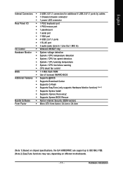
...port Š 1 PS/2 mouse port Š 1 parallel port Š 1 serial port Š 1 VGA port Š 4 USB 2.0/1.1 ports Š 1 RJ-45 port Š 3 audio jacks (Line In / Line Out / MIC In) I/O Control Š Winbond W83627 chip Hardware Monitor Š System voltage detection Š System / CPU temperature detection Š System... (OEM version) Form Factor Š Micro ATX form factor; 24.4cm x 24.4cm (Note 1) Based on chipset specifications, the GA-VM800PMC can support up to 800 MHz FSB. (Note 2) EasyTune functions may vary depending on different motherboards. - 11 -
...port Š 1 PS/2 mouse port Š 1 parallel port Š 1 serial port Š 1 VGA port Š 4 USB 2.0/1.1 ports Š 1 RJ-45 port Š 3 audio jacks (Line In / Line Out / MIC In) I/O Control Š Winbond W83627 chip Hardware Monitor Š System voltage detection Š System / CPU temperature detection Š System... (OEM version) Form Factor Š Micro ATX form factor; 24.4cm x 24.4cm (Note 1) Based on chipset specifications, the GA-VM800PMC can support up to 800 MHz FSB. (Note 2) EasyTune functions may vary depending on different motherboards. - 11 -
Manual
Page 16
... Line Out (Front Speaker Out) Connect the stereo speakers, earphone or front surround channels to the lower port (purple). GA-VM800PMC Motherboard - 16 - VGA Port Monitor can use audio software to configure 2-/4-/6- You can be connected to VGA port. can be connected to Line In jack. Serial Port Devices...MIC In Microphone can be connected to MIC In jack. If your OS or device(s) vendors. have a standard USB interface. channel audio functioning. Line In Devices like mouses, modems, and etc. Parallel Port The parallel port allows connection of 10/100 Mbps.
... Line Out (Front Speaker Out) Connect the stereo speakers, earphone or front surround channels to the lower port (purple). GA-VM800PMC Motherboard - 16 - VGA Port Monitor can use audio software to configure 2-/4-/6- You can be connected to VGA port. can be connected to Line In jack. Serial Port Devices...MIC In Microphone can be connected to MIC In jack. If your OS or device(s) vendors. have a standard USB interface. channel audio functioning. Line In Devices like mouses, modems, and etc. Parallel Port The parallel port allows connection of 10/100 Mbps.
Manual
Page 22
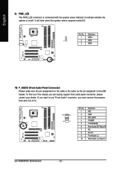
... 9-10. 10 9 2 1 Pin No. 1 2 3 4 5 6 7 8 9 10 Definition MIC GND MIC_BIAS POWER FrontAudio(R) Rear Audio (R)/ Return R NC No Pin FrontAudio (L) Rear Audio (L)/ Return L GA-VM800PMC Motherboard - 22 - Definition 1 MPD+ 1 2 MPD- 3 MPD- 10) F_AUDIO (Front Audio Panel Connector) Please make sure the pin assignment on the cable is the same as the pin... enters suspend mode(S1). English 9) PWR_LED The PWR_LED connector is connected with the system power indicator to use "Front Audio" connector, you are buying support front audio panel connector, please contact your dealer.
... 9-10. 10 9 2 1 Pin No. 1 2 3 4 5 6 7 8 9 10 Definition MIC GND MIC_BIAS POWER FrontAudio(R) Rear Audio (R)/ Return R NC No Pin FrontAudio (L) Rear Audio (L)/ Return L GA-VM800PMC Motherboard - 22 - Definition 1 MPD+ 1 2 MPD- 3 MPD- 10) F_AUDIO (Front Audio Panel Connector) Please make sure the pin assignment on the cable is the same as the pin... enters suspend mode(S1). English 9) PWR_LED The PWR_LED connector is connected with the system power indicator to use "Front Audio" connector, you are buying support front audio panel connector, please contact your dealer.

Manual
Page 23
... 23 - Use this feature only when your stereo system has digital input function. Pin No. Be careful with the polarity of providing digital audio to external speakers or compressed AC3 data to an external Dolby Digital Decoder. Hardware Installation English 11) CD_IN (CD IN Connector) Connect CD...-ROM or DVD-ROM audio out to work or even damage it. Definition 1 1 CD-L 2 GND 3 GND 4 CD-R 12) SPDIF_IO (S/PDIF In/Out Connector) The S/PDIF...
... 23 - Use this feature only when your stereo system has digital input function. Pin No. Be careful with the polarity of providing digital audio to external speakers or compressed AC3 data to an external Dolby Digital Decoder. Hardware Installation English 11) CD_IN (CD IN Connector) Connect CD...-ROM or DVD-ROM audio out to work or even damage it. Definition 1 1 CD-L 2 GND 3 GND 4 CD-R 12) SPDIF_IO (S/PDIF In/Out Connector) The S/PDIF...
Manual
Page 24
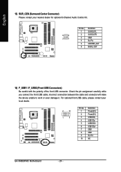
... No. 1 2 3 4 5 6 7 8 9 10 Definition Power(5V) Power(5V) USB0 DXUSB1 DyUSB0 DX+ USB1 Dy+ GND GND No Pin NC GA-VM800PMC Motherboard - 24 - For optional front USB cable, please contact your nearest dealer for optional 6-Channel Audio Combo Kit. 6 5 2 1 Pin No. 1 2 3 4 5 6 Definition SUR OUTL SUR OUTR GND No Pin CENTER_OUT BASS_OUT 14) F_USB1 / F_USB2...
... No. 1 2 3 4 5 6 7 8 9 10 Definition Power(5V) Power(5V) USB0 DXUSB1 DyUSB0 DX+ USB1 Dy+ GND GND No Pin NC GA-VM800PMC Motherboard - 24 - For optional front USB cable, please contact your nearest dealer for optional 6-Channel Audio Combo Kit. 6 5 2 1 Pin No. 1 2 3 4 5 6 Definition SUR OUTL SUR OUTR GND No Pin CENTER_OUT BASS_OUT 14) F_USB1 / F_USB2...
Manual
Page 34
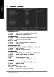
Disabled Disable this function. Enabled Enable USB 1.1 controller. (Default value) GA-VM800PMC Motherboard - 34 - IDE Set onboard SATA mode to IDE. (Default value) AC97 Audio Auto Enable onboard AC'97 audio function. (Default value) Disabled Disable this function. (Default value) OnChip Serial ATA ... Peripherals OnChip IDE Channel 0 OnChip IDE Channel 1 VIA Onboard LAN OnBoard LAN Boot ROM OnChip Serial ATA SATA Mode AC97 Audio USB 1.1 Controller USB 2.0 Controller USB Keyboard Support USB Mouse Support Legacy USB storage detect Onboard Serial Port 1 Onboard Serial...
Disabled Disable this function. Enabled Enable USB 1.1 controller. (Default value) GA-VM800PMC Motherboard - 34 - IDE Set onboard SATA mode to IDE. (Default value) AC97 Audio Auto Enable onboard AC'97 audio function. (Default value) Disabled Disable this function. (Default value) OnChip Serial ATA ... Peripherals OnChip IDE Channel 0 OnChip IDE Channel 1 VIA Onboard LAN OnBoard LAN Boot ROM OnChip Serial ATA SATA Mode AC97 Audio USB 1.1 Controller USB 2.0 Controller USB Keyboard Support USB Mouse Support Legacy USB storage detect Onboard Serial Port 1 Onboard Serial...
Manual
Page 62
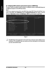
...2006 Award Software Integrated Peripherals OnChip IDE Channel 0 OnChip IDE Channel 1 VIA Onboard LAN OnBoard LAN Boot ROM OnChip Serial ATA SATA Mode AC97 Audio USB 1.1 Controller USB 2.0 Controller USB Keyboard Support USB Mouse Support Legacy USB storage detect Onboard Serial Port 1 Onboard Serial Port 2 Onboard ...The BIOS Setup menus described in system BIOS Setup and set this section may not show the exact settings for the SATA hard drive(s). GA-VM800PMC Motherboard - 62 - If you have to make sure whether the SATA controller is configured correctly in this item to RAID (IDE by ...
...2006 Award Software Integrated Peripherals OnChip IDE Channel 0 OnChip IDE Channel 1 VIA Onboard LAN OnBoard LAN Boot ROM OnChip Serial ATA SATA Mode AC97 Audio USB 1.1 Controller USB 2.0 Controller USB Keyboard Support USB Mouse Support Legacy USB storage detect Onboard Serial Port 1 Onboard Serial Port 2 Onboard ...The BIOS Setup menus described in system BIOS Setup and set this section may not show the exact settings for the SATA hard drive(s). GA-VM800PMC Motherboard - 62 - If you have to make sure whether the SATA controller is configured correctly in this item to RAID (IDE by ...
Manual
Page 73
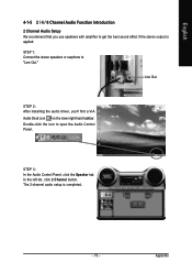
... effect if the stereo output is completed. - 73 - English 4-1-5 2 / 4 / 6 Channel Audio Function Introduction 2 Channel Audio Setup We recommend that you 'll find a VIA Audio Deck icon on the lower right hand taskbar. STEP 3: In the Audio Control Panel, click the Speaker tab. The 2-channel audio setup is applied. Appendix STEP 1: Connect the stereo speakers or...
... effect if the stereo output is completed. - 73 - English 4-1-5 2 / 4 / 6 Channel Audio Function Introduction 2 Channel Audio Setup We recommend that you 'll find a VIA Audio Deck icon on the lower right hand taskbar. STEP 3: In the Audio Control Panel, click the Speaker tab. The 2-channel audio setup is applied. Appendix STEP 1: Connect the stereo speakers or...
Manual
Page 74
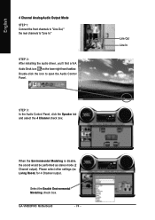
... Line In When the Environmental Modeling is disable, the sound would be performed as stereo mode (2 Channel output). Double-click the icon to "Line In." GA-VM800PMC Motherboard - 74 - English 4 Channel Analog Audio Output Mode STEP 1: Connect the front channels to "Line Out," the rear channels to open the...
... Line In When the Environmental Modeling is disable, the sound would be performed as stereo mode (2 Channel output). Double-click the icon to "Line In." GA-VM800PMC Motherboard - 74 - English 4 Channel Analog Audio Output Mode STEP 1: Connect the front channels to "Line Out," the rear channels to open the...
Manual
Page 75
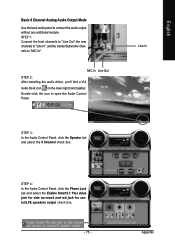
... Panel, click the Speaker tab and select the 6 Channel check box. STEP 4: In the Audio Control Panel, click the Phone Jack tab and select the Enable Smart5.1 Plus (blue jack for side surround and red jack for center/LFE speakers ...output check box. - 75 - MIC In Line Out STEP 2: After installing the audio driver, you'll find a VIA Audio Deck icon on the lower right hand taskbar. Appendix Double-click the icon to connect the audio output without any additional module. STEP 1: Connect the front channels to "Line Out",the rear...
... Panel, click the Speaker tab and select the 6 Channel check box. STEP 4: In the Audio Control Panel, click the Phone Jack tab and select the Enable Smart5.1 Plus (blue jack for side surround and red jack for center/LFE speakers ...output check box. - 75 - MIC In Line Out STEP 2: After installing the audio driver, you'll find a VIA Audio Deck icon on the lower right hand taskbar. Appendix Double-click the icon to connect the audio output without any additional module. STEP 1: Connect the front channels to "Line Out",the rear...
Manual
Page 76
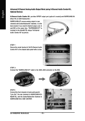
...In and MIC at the same time. GA-VM800PMC Motherboard - 76 - STEP 2: Connect the "SURROUND-KIT" cable to rear channels and Center/Subwoofer channels. English Advanced 6 Channel Analog Audio Output Mode (using 6-Channel Audio Combo Kit , Optional Device): 6-Channel Audio Combo Kit provides S/PDIF output port (optical... R/L & CEN /Subwoofer) SURROUND-KIT access analog output to the SUR_CEN connector on the M/B. STEP 3: Connect the front channels to back audio panel's "Line Out", the rear channels to SURROUND-Kit's REAR R/L, and the Center/Subwoofer channels to the chassis back panel with a ...
...In and MIC at the same time. GA-VM800PMC Motherboard - 76 - STEP 2: Connect the "SURROUND-KIT" cable to rear channels and Center/Subwoofer channels. English Advanced 6 Channel Analog Audio Output Mode (using 6-Channel Audio Combo Kit , Optional Device): 6-Channel Audio Combo Kit provides S/PDIF output port (optical... R/L & CEN /Subwoofer) SURROUND-KIT access analog output to the SUR_CEN connector on the M/B. STEP 3: Connect the front channels to back audio panel's "Line Out", the rear channels to SURROUND-Kit's REAR R/L, and the Center/Subwoofer channels to the chassis back panel with a ...
Manual
Page 77
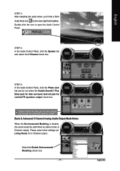
... box. - 77 - Appendix Double-click the icon to open the Audio Control Panel. English STEP 4: After installing the audio driver, you'll find a SVIA Audio Deck icon on the lower right hand taskbar. Basic & Advanced 6 Channel Analog Audio Output Mode Notes: When the Environmental Modeling is disable, the sound would... as stereo mode (2 Channel output). Please select other settings (ex: Living Room) for center/LFE speakers output check box. STEP 6: In the Audio Control Panel, click the Phone Jack tab and do not select the Enable Smart5.1 Plus (blue jack for side surround and red jack for 6 ...
... box. - 77 - Appendix Double-click the icon to open the Audio Control Panel. English STEP 4: After installing the audio driver, you'll find a SVIA Audio Deck icon on the lower right hand taskbar. Basic & Advanced 6 Channel Analog Audio Output Mode Notes: When the Environmental Modeling is disable, the sound would... as stereo mode (2 Channel output). Please select other settings (ex: Living Room) for center/LFE speakers output check box. STEP 6: In the Audio Control Panel, click the Phone Jack tab and do not select the Enable Smart5.1 Plus (blue jack for side surround and red jack for 6 ...


