Manual
Page 11
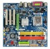
.../2 keyboard port Š 1 PS/2 mouse port Š 1 parallel port Š 1 serial port Š 1 VGA port Š 4 USB 2.0/1.1 ports Š 1 RJ-45 port Š 3 audio jacks (Line In / Line Out / MIC In) I/O Control Š Winbond W83627 chip Hardware Monitor Š System voltage detection Š System / CPU temperature detection Š System / CPU fan speed detection Š System / CPU warning temperature Š System / CPU fan failure warning Š CPU smart fan control BIOS Š 1 4 Mbit flash ROM Š Use of licensed AWARD BIOS Additional Features Š Supports...
.../2 keyboard port Š 1 PS/2 mouse port Š 1 parallel port Š 1 serial port Š 1 VGA port Š 4 USB 2.0/1.1 ports Š 1 RJ-45 port Š 3 audio jacks (Line In / Line Out / MIC In) I/O Control Š Winbond W83627 chip Hardware Monitor Š System voltage detection Š System / CPU temperature detection Š System / CPU fan speed detection Š System / CPU warning temperature Š System / CPU fan failure warning Š CPU smart fan control BIOS Š 1 4 Mbit flash ROM Š Use of licensed AWARD BIOS Additional Features Š Supports...

Manual
Page 13
... boxed fan) Fig. 3 Place the CPU cooler atop the CPU and make sure the Male and Female push pin are joined closely. (for detailed installation instructions, please refer to the CPU as the picture, the installation is only for heat dissipation or using extreme care when removing the CPU cooler. - 13 - The CPU cooler may adhere to the CPU cooler installation section of the user manual...
... boxed fan) Fig. 3 Place the CPU cooler atop the CPU and make sure the Male and Female push pin are joined closely. (for detailed installation instructions, please refer to the CPU as the picture, the installation is only for heat dissipation or using extreme care when removing the CPU cooler. - 13 - The CPU cooler may adhere to the CPU cooler installation section of the user manual...
Manual
Page 20
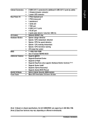
... to connect two IDE devices, please set the jumper on one IDE cable, and the single IDE cable can then connect to two IDE devices (hard drive or optical drive). English 6) IDE1 / IDE2 (IDE Connector) An IDE device connects to 150MB/s transfer rate. Please refer to the BIOS setting for information on settings, please refer to work properly. SATA1 1 7 1 7 SATA0 Pin No. 1 2 3 4 5 6 7 Definition GND TXP TXN GND RXN RXP GND GA-VM800PMC Motherboard - 20 - Before attaching the IDE cable, please...
... to connect two IDE devices, please set the jumper on one IDE cable, and the single IDE cable can then connect to two IDE devices (hard drive or optical drive). English 6) IDE1 / IDE2 (IDE Connector) An IDE device connects to 150MB/s transfer rate. Please refer to the BIOS setting for information on settings, please refer to work properly. SATA1 1 7 1 7 SATA0 Pin No. 1 2 3 4 5 6 7 Definition GND TXP TXN GND RXN RXP GND GA-VM800PMC Motherboard - 20 - Before attaching the IDE cable, please...
Manual
Page 28
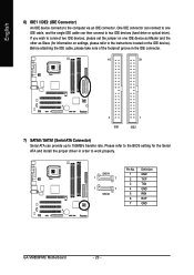
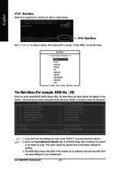
.../PCI Configurations ` PC Health Status Load Fail-Safe Defaults Load Optimized Defaults Set Supervisor Password Set User Password Save & Exit Setup Exit Without Saving Esc: Quit F8: Q-Flash KLJI: Select Item F10: Save & Exit Setup Time, Date, Hard Disk Type... 1. The BIOS Setup menus described in the BIOS Setup when somehow the system is not stable as figure below) will appear on cards) device. Boot Menu == Select a Boot First device == Floppy LS120 Hard Disk CDROM ZIP USB-FDD USB-ZIP USB-CDROM USB-HDD LAN KL:Move Enter...
.../PCI Configurations ` PC Health Status Load Fail-Safe Defaults Load Optimized Defaults Set Supervisor Password Set User Password Save & Exit Setup Exit Without Saving Esc: Quit F8: Q-Flash KLJI: Select Item F10: Save & Exit Setup Time, Date, Hard Disk Type... 1. The BIOS Setup menus described in the BIOS Setup when somehow the system is not stable as figure below) will appear on cards) device. Boot Menu == Select a Boot First device == Floppy LS120 Hard Disk CDROM ZIP USB-FDD USB-ZIP USB-CDROM USB-HDD LAN KL:Move Enter...
Manual
Page 30
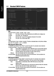
.../Auto(default:Auto) IDE Channel 2/3 Master IDE HDD Auto-Detection Press "Enter" to select this to automatically detect SATA IDE devices during POST. • None (Default value) Select this option for the hard drive. time clock. For example, 1 p.m. English 2-1 Standard CMOS Features Date (mm:dd:yy) Time (hh:mm:ss) CMOS Setup Utility-Copyright (C) 1984-2006 Award Software Standard CMOS Features Wed, Nov 22 2006 10:40:9 Item Help Menu Level` ` IDE Channel 0 Master ` IDE Channel 0 Slave ` IDE Channel 1 Master ` IDE Channel 1 Slave ` IDE Channel 2 Master ` IDE Channel...
.../Auto(default:Auto) IDE Channel 2/3 Master IDE HDD Auto-Detection Press "Enter" to select this to automatically detect SATA IDE devices during POST. • None (Default value) Select this option for the hard drive. time clock. For example, 1 p.m. English 2-1 Standard CMOS Features Date (mm:dd:yy) Time (hh:mm:ss) CMOS Setup Utility-Copyright (C) 1984-2006 Award Software Standard CMOS Features Wed, Nov 22 2006 10:40:9 Item Help Menu Level` ` IDE Channel 0 Master ` IDE Channel 0 Slave ` IDE Channel 1 Master ` IDE Channel 1 Slave ` IDE Channel 2 Master ` IDE Channel...
Manual
Page 32
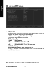
... CMOS Setup Utility-Copyright (C) 1984-2006 Award Software Advanced BIOS Features Init Display First VGA Share Memory Size ` Hard Disk Boot Priority First Boot Device Second Boot Device Third Boot Device Password Check CPU Hyper-Threading (Note) Limit CPUID Max. VGA Share Memory Size Disabled Disable this function. 16M Set VGA share memory size to 16 MB. 32M Set VGA share memory size to 32 MB. 64M Set VGA share memory size to move it down the list. Use < > or < > to select a device, then press to move it up when you install a PCI card and a PCI Express VGA card...
... CMOS Setup Utility-Copyright (C) 1984-2006 Award Software Advanced BIOS Features Init Display First VGA Share Memory Size ` Hard Disk Boot Priority First Boot Device Second Boot Device Third Boot Device Password Check CPU Hyper-Threading (Note) Limit CPUID Max. VGA Share Memory Size Disabled Disable this function. 16M Set VGA share memory size to 16 MB. 32M Set VGA share memory size to 32 MB. 64M Set VGA share memory size to move it down the list. Use < > or < > to select a device, then press to move it up when you install a PCI card and a PCI Express VGA card...
Manual
Page 36
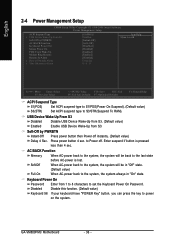
...) Set ACPI suspend type to Power off instantly. (Default value) Delay 4 Sec. USB Device Wake-Up From S3 Disabled Disable USB Device Wake-Up from S3. (Default value) Enabled Enable USB Device Wake-Up from 1 to 8 characters to the system, the system always in "On" state. Enter suspend if button is lost. English 2-4 Power Management Setup CMOS Setup Utility-Copyright (C) 1984-2006 Award Software Power Management Setup ACPI Suspend Type x USB Device Wake-Up From S3 Soft-Off by PWRBTN AC BACK Function Keyboard Power On Mouse Power...
...) Set ACPI suspend type to Power off instantly. (Default value) Delay 4 Sec. USB Device Wake-Up From S3 Disabled Disable USB Device Wake-Up from S3. (Default value) Enabled Enable USB Device Wake-Up from 1 to 8 characters to the system, the system always in "On" state. Enter suspend if button is lost. English 2-4 Power Management Setup CMOS Setup Utility-Copyright (C) 1984-2006 Award Software Power Management Setup ACPI Suspend Type x USB Device Wake-Up From S3 Soft-Off by PWRBTN AC BACK Function Keyboard Power On Mouse Power...

Manual
Page 39
... Disabled Don't reset case open status. (Default value) Enabled Clear case open status at 80oC / 176oF. Current Voltage(V) VCORE / DDR POWER / +3.3V / +12V Detect system's voltage status automatically. Monitor system temperature at next boot. Case Opened If the case is closed, "Case Opened" will show "No". BIOS Setup English 2-6 PC Health Status CMOS Setup Utility-Copyright (C) 1984-2006 Award Software PC Health Status Reset Case Open Status Case Opened VCORE DDR POWER +3.3V +12V System Temperature CPU Temperature Current SYS FAN Speed...
... Disabled Don't reset case open status. (Default value) Enabled Clear case open status at 80oC / 176oF. Current Voltage(V) VCORE / DDR POWER / +3.3V / +12V Detect system's voltage status automatically. Monitor system temperature at next boot. Case Opened If the case is closed, "Case Opened" will show "No". BIOS Setup English 2-6 PC Health Status CMOS Setup Utility-Copyright (C) 1984-2006 Award Software PC Health Status Reset Case Open Status Case Opened VCORE DDR POWER +3.3V +12V System Temperature CPU Temperature Current SYS FAN Speed...
Manual
Page 42
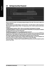
... . Type the password, up to abort the selection and not enter a password. To disable password, just press when you to specify two separate passwords: SUPERVISOR PASSWORD and a USER PASSWORD. The BIOS Setup program allows you are prompted to enter password. GA-VM800PMC Motherboard - 42 - English 2-9 Set Supervisor/User Password CMOS Setup Utility-Copyright (C) 1984-2006 Award Software ` Standard CMOS Features ` Advanced BIOS Features ` Integrated Peripherals ` Power Management Setup ` PnP/PCI ConfigurationEsnter Password: ` PC Health Status Load Fail-Safe Defaults Load Optimized...
... . Type the password, up to abort the selection and not enter a password. To disable password, just press when you to specify two separate passwords: SUPERVISOR PASSWORD and a USER PASSWORD. The BIOS Setup program allows you are prompted to enter password. GA-VM800PMC Motherboard - 42 - English 2-9 Set Supervisor/User Password CMOS Setup Utility-Copyright (C) 1984-2006 Award Software ` Standard CMOS Features ` Advanced BIOS Features ` Integrated Peripherals ` Power Management Setup ` PnP/PCI ConfigurationEsnter Password: ` PC Health Status Load Fail-Safe Defaults Load Optimized...
Manual
Page 50
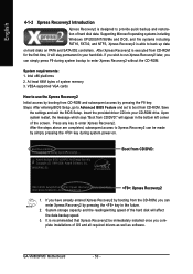
... driver CD into your hard disk. System requirements: 1. If you complete installations of OS and all required drivers as well as software. VESA-supported VGA cards How to use the Xpress Recovery2 Initial access by booting from CD-ROM and subsequent access by pressing the F9 key: Steps: After entering BIOS Setup, go to Advanced BIOS Feature and set to boot from CD/DVD: Press any key to startup XpressRecovery2..... Boot from CD-ROM. Award Modular BIOS...
... driver CD into your hard disk. System requirements: 1. If you complete installations of OS and all required drivers as well as software. VESA-supported VGA cards How to use the Xpress Recovery2 Initial access by booting from CD-ROM and subsequent access by pressing the F9 key: Steps: After entering BIOS Setup, go to Advanced BIOS Feature and set to boot from CD/DVD: Press any key to startup XpressRecovery2..... Boot from CD-ROM. Award Modular BIOS...

Manual
Page 53
...CMOS Setup Utility-Copyright (C) 1984-2004 Award Software Standard CMOS Features Advanced BIOS Features Integrated Peripherals Power Management Setup PnP/PCI Configurations PC Health Status MB Intelligent Tweaker(M.I.T.) ESC: Quit F8: Dual BIOS/Q-Flash Select Language Load Fail-Safe Defaults Load Optimized Defaults Set Supervisor Password Set User Password Save & Exit Setup Exit Without Saving F3: Change Language F10: Save & Exit Setup Time, Date, Hard Disk Type... Pressing the buttons mentioned on your keyboards to Floppy Enter : Run :Move ESC:Reset F10:Power Off Dual BIOS...
...CMOS Setup Utility-Copyright (C) 1984-2004 Award Software Standard CMOS Features Advanced BIOS Features Integrated Peripherals Power Management Setup PnP/PCI Configurations PC Health Status MB Intelligent Tweaker(M.I.T.) ESC: Quit F8: Dual BIOS/Q-Flash Select Language Load Fail-Safe Defaults Load Optimized Defaults Set Supervisor Password Set User Password Save & Exit Setup Exit Without Saving F3: Change Language F10: Save & Exit Setup Time, Date, Hard Disk Type... Pressing the buttons mentioned on your keyboards to Floppy Enter : Run :Move ESC:Reset F10:Power Off Dual BIOS...

Manual
Page 55
... flashed. The BIOS file becomes Fba after you exit Q-Flash. The progress of updating BIOS will begin to update BIOS. Press any keys to return to flash the backup BIOS, too. 5. Halt On Error Disable CPolpeyasMe apirneRssOaMnyDkaetya to cBoanctkiunpue Load Default Settings Save Settings to CMOS Q-Flash Utility Load Main BIOS from Floppy Load Backup BIOS from Floppy Save Main BIOS to Floppy Save Backup BIOS to Floppy Enter : Run :Move ESC:Reset F10:Power Off After system reboots, you may find the BIOS version on your boot screen...
... flashed. The BIOS file becomes Fba after you exit Q-Flash. The progress of updating BIOS will begin to update BIOS. Press any keys to return to flash the backup BIOS, too. 5. Halt On Error Disable CPolpeyasMe apirneRssOaMnyDkaetya to cBoanctkiunpue Load Default Settings Save Settings to CMOS Q-Flash Utility Load Main BIOS from Floppy Load Backup BIOS from Floppy Save Main BIOS to Floppy Save Backup BIOS to Floppy Enter : Run :Move ESC:Reset F10:Power Off After system reboots, you may find the BIOS version on your boot screen...
Manual
Page 56
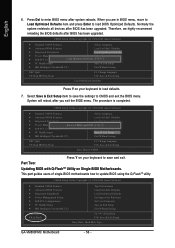
.... Part Two: Updating BIOS with Q-FlashTM Utility on your keyboard to enter BIOS menu after you are in BIOS menu, move to Load Optimized Defaults item and press Enter to update BIOS using the Q-FlashTM utility. Normally the system redetects all devices after BIOS has been upgraded. CMOS Setup Utility-Copyright (C) 1984-2004 Award Software Standard CMOS Features Select Language Advanced BIOS Features Load Fail-Safe Defaults Integrated Peripherals Load Optimized Defaults Power Management Setup Save to CMOS and EXIT (SYe/tNS)u?pYervisor Password PnP/PCI Configurations Set User...
.... Part Two: Updating BIOS with Q-FlashTM Utility on your keyboard to enter BIOS menu after you are in BIOS menu, move to Load Optimized Defaults item and press Enter to update BIOS using the Q-FlashTM utility. Normally the system redetects all devices after BIOS has been upgraded. CMOS Setup Utility-Copyright (C) 1984-2004 Award Software Standard CMOS Features Select Language Advanced BIOS Features Load Fail-Safe Defaults Integrated Peripherals Load Optimized Defaults Power Management Setup Save to CMOS and EXIT (SYe/tNS)u?pYervisor Password PnP/PCI Configurations Set User...
Manual
Page 62
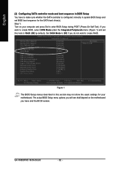
... BIOS Setup during POST (Power-On Self Test). GA-VM800PMC Motherboard - 62 - CMOS Setup Utility-Copyright (C) 1984-2006 Award Software Integrated Peripherals OnChip IDE Channel 0 OnChip IDE Channel 1 VIA Onboard LAN OnBoard LAN Boot ROM OnChip Serial ATA SATA Mode AC97 Audio USB 1.1 Controller USB 2.0 Controller USB Keyboard Support USB Mouse Support Legacy USB storage detect Onboard Serial Port 1 Onboard Serial Port 2 Onboard Parallel Port Parallel Port Mode x EPP Mode Select [Enabled] [Enabled] [Enabled] [Disabled] [Enabled] [RAID] [Auto] [Enabled] [Enabled] [Disabled] [Disabled] [Enabled...
... BIOS Setup during POST (Power-On Self Test). GA-VM800PMC Motherboard - 62 - CMOS Setup Utility-Copyright (C) 1984-2006 Award Software Integrated Peripherals OnChip IDE Channel 0 OnChip IDE Channel 1 VIA Onboard LAN OnBoard LAN Boot ROM OnChip Serial ATA SATA Mode AC97 Audio USB 1.1 Controller USB 2.0 Controller USB Keyboard Support USB Mouse Support Legacy USB storage detect Onboard Serial Port 1 Onboard Serial Port 2 Onboard Parallel Port Parallel Port Mode x EPP Mode Select [Enabled] [Enabled] [Enabled] [Disabled] [Enabled] [RAID] [Auto] [Enabled] [Enabled] [Disabled] [Disabled] [Enabled...
Manual
Page 69
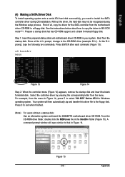
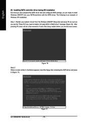
...-ROM to a floppy disk. English (4) Making a SATA Driver Disk To install operating system onto a serial ATA hard disk successfully, you need to install the SATA controller driver during the Windows setup process. First of all, copy the driver for Windows operating system. Step 1: Insert the prepared startup disk and motherboard driver CD-ROM in MS-DOS mode(Note). See the instructions below about how to the floppy disk. Prepare a startup disk that in Figure 14. Boot from the menu...
...-ROM to a floppy disk. English (4) Making a SATA Driver Disk To install operating system onto a serial ATA hard disk successfully, you need to install the SATA controller driver during the Windows setup process. First of all, copy the driver for Windows operating system. Step 1: Insert the prepared startup disk and motherboard driver CD-ROM in MS-DOS mode(Note). See the instructions below about how to the floppy disk. Prepare a startup disk that in Figure 14. Boot from the menu...
Manual
Page 70
... 17 GA-VM800PMC Motherboard - 70 - Windows Setup Setup could not determine the type of Windows XP installation. The following mass storage devices(s) * To specify additional SCSI adapters, CD-ROM drives, or special disk controllers for use with Windows, including those for use with the SATA driver. Windows Setup Press F6 if you see the next screen. Figure 16 Step 2: When a screen similar to that you have prepared the SATA driver disk and configured BIOS settings, you have chosen to install Windows 2000...
... 17 GA-VM800PMC Motherboard - 70 - Windows Setup Setup could not determine the type of Windows XP installation. The following mass storage devices(s) * To specify additional SCSI adapters, CD-ROM drives, or special disk controllers for use with Windows, including those for use with the SATA driver. Windows Setup Press F6 if you see the next screen. Figure 16 Step 2: When a screen similar to that you have prepared the SATA driver disk and configured BIOS settings, you have chosen to install Windows 2000...
Manual
Page 73
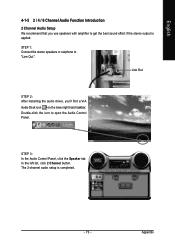
... the Audio Control Panel. Line Out STEP 2: After installing the audio driver, you use speakers with amplifier to get the best sound effect if the stereo output is completed. - 73 - English 4-1-5 2 / 4 / 6 Channel Audio Function Introduction 2 Channel Audio Setup We recommend that you 'll find a VIA Audio Deck icon on the lower right hand taskbar. STEP 3: In the Audio Control Panel, click the Speaker tab. In the left list, click 2 Channel button. Double...
... the Audio Control Panel. Line Out STEP 2: After installing the audio driver, you use speakers with amplifier to get the best sound effect if the stereo output is completed. - 73 - English 4-1-5 2 / 4 / 6 Channel Audio Function Introduction 2 Channel Audio Setup We recommend that you 'll find a VIA Audio Deck icon on the lower right hand taskbar. STEP 3: In the Audio Control Panel, click the Speaker tab. In the left list, click 2 Channel button. Double...
Manual
Page 74
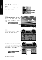
... Modeling is disable, the sound would be performed as stereo mode (2 Channel output). Please select other settings (ex: Living Room) for 4 Channel output. STEP 3: In the Audio Control Panel, click the Speaker tab and select the 4 Channel check box. Select the Enable Environmental Modeling check box. English 4 Channel Analog Audio Output Mode STEP 1: Connect the front channels to "Line Out," the rear channels to open the Audio Control Panel. GA-VM800PMC Motherboard - 74 - STEP 2: After installing the audio driver...
... Modeling is disable, the sound would be performed as stereo mode (2 Channel output). Please select other settings (ex: Living Room) for 4 Channel output. STEP 3: In the Audio Control Panel, click the Speaker tab and select the 4 Channel check box. Select the Enable Environmental Modeling check box. English 4 Channel Analog Audio Output Mode STEP 1: Connect the front channels to "Line Out," the rear channels to open the Audio Control Panel. GA-VM800PMC Motherboard - 74 - STEP 2: After installing the audio driver...
Manual
Page 77
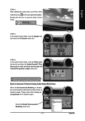
... Enable Environmental Modeling check box. - 77 - Basic & Advanced 6 Channel Analog Audio Output Mode Notes: When the Environmental Modeling is disable, the sound would be performed as stereo mode (2 Channel output). Appendix STEP 6: In the Audio Control Panel, click the Phone Jack tab and do not select the Enable Smart5.1 Plus (blue jack for side surround and red jack for 6 Channel output. English STEP 4: After installing the audio driver...
... Enable Environmental Modeling check box. - 77 - Basic & Advanced 6 Channel Analog Audio Output Mode Notes: When the Environmental Modeling is disable, the sound would be performed as stereo mode (2 Channel output). Appendix STEP 6: In the Audio Control Panel, click the Phone Jack tab and do not select the Enable Smart5.1 Plus (blue jack for side surround and red jack for 6 Channel output. English STEP 4: After installing the audio driver...
Manual
Page 78
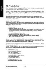
... after updating BIOS. AWARD BIOS Beep Codes 1 short: System boots successfully 2 short: CMOS setting error 1 long 1 short: DRAM or M/B error 1 long 2 short: Monitor or display card error 1 long 3 short: Keyboard error 1 long 9 short: BIOS ROM error Continuous long beeps: DRAM error Continuous short beeps: Power error GA-VM800PMC Motherboard - 78 - Re-insert the battery to case. Answer: Please make sure the speaker you are hidden in the battery holder to connect the positive and negative pins in new BIOS version. If not, please change another speaker with an internal amplifier...
... after updating BIOS. AWARD BIOS Beep Codes 1 short: System boots successfully 2 short: CMOS setting error 1 long 1 short: DRAM or M/B error 1 long 2 short: Monitor or display card error 1 long 3 short: Keyboard error 1 long 9 short: BIOS ROM error Continuous long beeps: DRAM error Continuous short beeps: Power error GA-VM800PMC Motherboard - 78 - Re-insert the battery to case. Answer: Please make sure the speaker you are hidden in the battery holder to connect the positive and negative pins in new BIOS version. If not, please change another speaker with an internal amplifier...


