Manual
Page 4
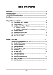
...GA-VM800PMC Motherboard Layout 7 Block Diagram ...8 Chapter 1 Hardware Installation 9 1-1 Considerations Prior to Installation 9 1-2 Feature Summary 10 1-3 Installation of the CPU and CPU Cooler 12 1-3-1 Installation of the CPU 12 1-3-2 Installation of the CPU Cooler 13 1-4 Installation of Memory 14 1-5 Installation of Expansion Cards 15 1-6 I/O Back Panel Introduction 16 1-7 Connectors Introduction 17 Chapter 2 BIOS... Setup 27 The Main Menu (For example: BIOS Ver. : D5 28 2-1 Standard CMOS Features 30 2-2 Advanced BIOS Features 32 2-3 ...
...GA-VM800PMC Motherboard Layout 7 Block Diagram ...8 Chapter 1 Hardware Installation 9 1-1 Considerations Prior to Installation 9 1-2 Feature Summary 10 1-3 Installation of the CPU and CPU Cooler 12 1-3-1 Installation of the CPU 12 1-3-2 Installation of the CPU Cooler 13 1-4 Installation of Memory 14 1-5 Installation of Expansion Cards 15 1-6 I/O Back Panel Introduction 16 1-7 Connectors Introduction 17 Chapter 2 BIOS... Setup 27 The Main Menu (For example: BIOS Ver. : D5 28 2-1 Standard CMOS Features 30 2-2 Advanced BIOS Features 32 2-3 ...

Manual
Page 5
Chapter 3 Drivers Installation 45 3-1 Install Chipset Drivers 45 3-2 SoftwareApplication 46 3-3 Software Information 46 3-4 Hardware Information 47 3-5 Contact Us ...47 Chapter 4 Appendix 49 4-1 Unique Software Utilities 49 4-1-1 EasyTune 5 Introduction 49 4-1-2 Xpress Recovery2 Introduction 50 4-1-3 Flash BIOS Method Introduction 52 4-1-4 Configuring SATA Hard Drive(s 61 4-1-5 2 / 4 / 6 Channel Audio Function Introduction 73 4-2 Troubleshooting 78 - 5 -
Chapter 3 Drivers Installation 45 3-1 Install Chipset Drivers 45 3-2 SoftwareApplication 46 3-3 Software Information 46 3-4 Hardware Information 47 3-5 Contact Us ...47 Chapter 4 Appendix 49 4-1 Unique Software Utilities 49 4-1-1 EasyTune 5 Introduction 49 4-1-2 Xpress Recovery2 Introduction 50 4-1-3 Flash BIOS Method Introduction 52 4-1-4 Configuring SATA Hard Drive(s 61 4-1-5 2 / 4 / 6 Channel Audio Function Introduction 73 4-2 Troubleshooting 78 - 5 -
Manual
Page 11
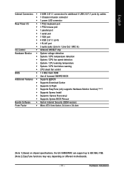
... CPU warning temperature Š System / CPU fan failure warning Š CPU smart fan control BIOS Š 1 4 Mbit flash ROM Š Use of licensed AWARD BIOS Additional Features Š Supports @BIOS Š Supports Download Center Š Supports Q-Flash Š Supports EasyTune (only supports Hardware ...138; Supports Xpress Recovery2 Š Supports Xpress BIOS Rescue Bundle Software Š Norton Internet Security (OEM version) Form Factor Š Micro ATX form factor; 24.4cm x 24.4cm (Note 1) Based on chipset specifications, the GA-VM800PMC can support up to 800 MHz FSB. (Note...
... CPU warning temperature Š System / CPU fan failure warning Š CPU smart fan control BIOS Š 1 4 Mbit flash ROM Š Use of licensed AWARD BIOS Additional Features Š Supports @BIOS Š Supports Download Center Š Supports Q-Flash Š Supports EasyTune (only supports Hardware ...138; Supports Xpress Recovery2 Š Supports Xpress BIOS Rescue Bundle Software Š Norton Internet Security (OEM version) Form Factor Š Micro ATX form factor; 24.4cm x 24.4cm (Note 1) Based on chipset specifications, the GA-VM800PMC can support up to 800 MHz FSB. (Note...
Manual
Page 12
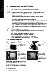
... occurs, please change the insert direction of the CPU. Fig. 4 Once the CPU is installed on the CPU socket to the CPU during installation.) GA-VM800PMC Motherboard - 12 - BIOS: A BIOS that might cause damage to the upright position. Chipset: An Intel® Chipset that has optimizations for HT Technology 1-3-1 Installation of the CPU Metal...
... occurs, please change the insert direction of the CPU. Fig. 4 Once the CPU is installed on the CPU socket to the CPU during installation.) GA-VM800PMC Motherboard - 12 - BIOS: A BIOS that might cause damage to the upright position. Chipset: An Intel® Chipset that has optimizations for HT Technology 1-3-1 Installation of the CPU Metal...
Manual
Page 14
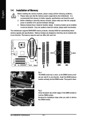
... are designed so that the computer power is supported by the motherboard. The motherboard supports DDRII/DDR memory modules, whereby BIOS will automatically detect memory capacity and specifications. Before installing or removing memory modules, please make sure that memory of similar ...unable to insert the module, please switch the direction. English DDRII DDR 1-4 Installation of the DIMM sockets to lock the DIMM module. GA-VM800PMC Motherboard - 14 - Please make sure that they can differ with the following conditions: 1. It is recommended that the memory used . ...
... are designed so that the computer power is supported by the motherboard. The motherboard supports DDRII/DDR memory modules, whereby BIOS will automatically detect memory capacity and specifications. Before installing or removing memory modules, please make sure that memory of similar ...unable to insert the module, please switch the direction. English DDRII DDR 1-4 Installation of the DIMM sockets to lock the DIMM module. GA-VM800PMC Motherboard - 14 - Please make sure that they can differ with the following conditions: 1. It is recommended that the memory used . ...

Manual
Page 15
...below: 1. English 1-5 Installation of the AGP slot when you try to install/uninstall the VGA card. Power on the slot. Install related driver from BIOS. 8. Make sure your expansion card by the small white-drawable bar. - 15 - Read the related expansion card's instruction document before installing the ... system. Hardware Installation Replace the screw to the onboard AGP slot and press firmly down on the computer, if necessary, setup BIOS utility of the expansion card. 6. Remove your computer's chassis cover. 7. Press the expansion card firmly into the computer. 2.
...below: 1. English 1-5 Installation of the AGP slot when you try to install/uninstall the VGA card. Power on the slot. Install related driver from BIOS. 8. Make sure your expansion card by the small white-drawable bar. - 15 - Read the related expansion card's instruction document before installing the ... system. Hardware Installation Replace the screw to the onboard AGP slot and press firmly down on the computer, if necessary, setup BIOS utility of the expansion card. 6. Remove your computer's chassis cover. 7. Press the expansion card firmly into the computer. 2.
Manual
Page 20
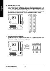
... optical drive). Please refer to the BIOS setting for information on settings, please refer to the instructions located on one IDE cable, and the single IDE cable can provide up to work properly. SATA1 1 7 1 7 SATA0 Pin No. 1 2 3 4 5 6 7 Definition GND TXP TXN GND RXN RXP GND GA-VM800PMC Motherboard - 20 - Before attaching the IDE...
... optical drive). Please refer to the BIOS setting for information on settings, please refer to the instructions located on one IDE cable, and the single IDE cable can provide up to work properly. SATA1 1 7 1 7 SATA0 Pin No. 1 2 3 4 5 6 7 Definition GND TXP TXN GND RXN RXP GND GA-VM800PMC Motherboard - 20 - Before attaching the IDE...

Manual
Page 25
English 15) COMB (COMB Connector) Be careful with the polarity of the COMB connector. Pin No. Please contact your nearest dealer for optional COMB cable. 9 1 10 2 Pin No. 1 2 3 4 5 6 7 8 9 10 Definition NDCDBNSINB NSOUTB NDTRBGND NDSRBNRTSBNCTSBNRIBNo Pin 16) CI (Chassis Intrusion, Case Open) This 2-pin connector allows your system to detect if the chassis cover is removed. Hardware Installation You can check the "Case Opened" status in BIOS Setup. Check the pin assignments while you connect the COMB cable. Definition 1 GND 1 2 Signal - 25 -
English 15) COMB (COMB Connector) Be careful with the polarity of the COMB connector. Pin No. Please contact your nearest dealer for optional COMB cable. 9 1 10 2 Pin No. 1 2 3 4 5 6 7 8 9 10 Definition NDCDBNSINB NSOUTB NDTRBGND NDSRBNRTSBNCTSBNRIBNo Pin 16) CI (Chassis Intrusion, Case Open) This 2-pin connector allows your system to detect if the chassis cover is removed. Hardware Installation You can check the "Case Opened" status in BIOS Setup. Check the pin assignments while you connect the COMB cable. Definition 1 GND 1 2 Signal - 25 -

Manual
Page 27
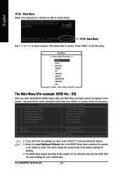
... select item Select Item Main Menu - When the power is a Windows-based utility that does not require users to boot to a new BIOS, either Gigabyte's Q-Flash or @BIOS utility can enter the BIOS setup screen by pressing "Ctrl + F1". The CMOS SETUP saves the configuration in system malfunction. - 27 - When the power is displayed...
... select item Select Item Main Menu - When the power is a Windows-based utility that does not require users to boot to a new BIOS, either Gigabyte's Q-Flash or @BIOS utility can enter the BIOS setup screen by pressing "Ctrl + F1". The CMOS SETUP saves the configuration in system malfunction. - 27 - When the power is displayed...
Manual
Page 28
...Password Save & Exit Setup Exit Without Saving Esc: Quit F8: Q-Flash KLJI: Select Item F10: Save & Exit Setup Time, Date, Hard Disk Type... 1. VM800PMC D5 . . . . :BIOS Setup/Q-Flash, : Xpress Recovery2, : Boot Menu 10/31/2006-P4M800Pro-823-6A7L6G0FC-00 : Boot Menu Use < > or < > to select a device,...to select among the items and press to access advanced options. 2. The BIOS Setup menus described in the BIOS Setup when somehow the system is not stable as figure below) will appear on cards) device. GA-VM800PMC Motherboard - 28 - Press to exit this chapter are for reference only and...
...Password Save & Exit Setup Exit Without Saving Esc: Quit F8: Q-Flash KLJI: Select Item F10: Save & Exit Setup Time, Date, Hard Disk Type... 1. VM800PMC D5 . . . . :BIOS Setup/Q-Flash, : Xpress Recovery2, : Boot Menu 10/31/2006-P4M800Pro-823-6A7L6G0FC-00 : Boot Menu Use < > or < > to select a device,...to select among the items and press to access advanced options. 2. The BIOS Setup menus described in the BIOS Setup when somehow the system is not stable as figure below) will appear on cards) device. GA-VM800PMC Motherboard - 28 - Press to exit this chapter are for reference only and...

Manual
Page 29
... the system parameters which the system would be in best performance configuration. „ Set Supervisor Password Change, set , or disable password. BIOS Setup It allows you to limit access to the system. „ Save & Exit Setup Save CMOS value settings to Setup. „...Password Change, set , or disable password. English „ Standard CMOS Features This setup page includes all the items in standard compatible BIOS. „ Advanced BIOS Features This setup page includes all the items of Award special enhanced features. „ Integrated Peripherals This setup page includes all onboard ...
... the system parameters which the system would be in best performance configuration. „ Set Supervisor Password Change, set , or disable password. BIOS Setup It allows you to limit access to the system. „ Save & Exit Setup Save CMOS value settings to Setup. „...Password Change, set , or disable password. English „ Standard CMOS Features This setup page includes all the items in standard compatible BIOS. „ Advanced BIOS Features This setup page includes all the items of Award special enhanced features. „ Integrated Peripherals This setup page includes all onboard ...
Manual
Page 30
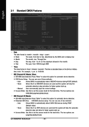
... automatic detection step and allow for faster system start up . • Manual User can use one of three methods: • Auto Allows BIOS to automatically detect IDE/SATA devices during POST. • None (Default value) Select this to set the access mode for the hard drive....Dec. IDE Channel 0/1 Master, Slave IDE HDD Auto-Detection Press "Enter" to select this if no IDE/SATA devices are : Large/Auto(default:Auto) GA-VM800PMC Motherboard - 30 - English 2-1 Standard CMOS Features Date (mm:dd:yy) Time (hh:mm:ss) CMOS Setup Utility-Copyright (C) 1984-2006 Award Software ...
... automatic detection step and allow for faster system start up . • Manual User can use one of three methods: • Auto Allows BIOS to automatically detect IDE/SATA devices during POST. • None (Default value) Select this to set the access mode for the hard drive....Dec. IDE Channel 0/1 Master, Slave IDE HDD Auto-Detection Press "Enter" to select this if no IDE/SATA devices are : Large/Auto(default:Auto) GA-VM800PMC Motherboard - 30 - English 2-1 Standard CMOS Features Date (mm:dd:yy) Time (hh:mm:ss) CMOS Setup Utility-Copyright (C) 1984-2006 Award Software ...

Manual
Page 31
...5.25 inch AT-type high-density drive; 1.2M byte capacity (3.5 inch when 3 Mode is 3 mode Floppy Drive. Base Memory The POST of the BIOS will determine the amount of the base memory is typically 512K for systems with 512K memory installed on the motherboard, or 640K for Japan Area...a keyboard or disk error; Memory The category is display-only which is the amount of the BIOS. Whenever the BIOS detects a non-fatal error the system will be labeled on the motherboard. BIOS Setup Hard drive information should be stopped. it will stop for a disk error; it will ...
...5.25 inch AT-type high-density drive; 1.2M byte capacity (3.5 inch when 3 Mode is 3 mode Floppy Drive. Base Memory The POST of the BIOS will determine the amount of the base memory is typically 512K for systems with 512K memory installed on the motherboard, or 640K for Japan Area...a keyboard or disk error; Memory The category is display-only which is the amount of the BIOS. Whenever the BIOS detects a non-fatal error the system will be labeled on the motherboard. BIOS Setup Hard drive information should be stopped. it will stop for a disk error; it will ...
Manual
Page 32
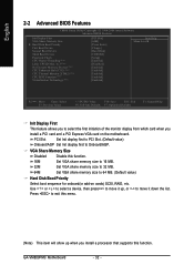
...menu. (Note) This item will show up when you install a PCI card and a PCI Express VGA card on cards) SCSI, RAID, etc. GA-VM800PMC Motherboard - 32 - VGA Share Memory Size Disabled Disable this function. PCI Slot Set Init display first to PCI Slot. (Default value) Onboard/AGP Set... share memory size to 32 MB. 64M Set VGA share memory size to Onboard/AGP. English 2-2 Advanced BIOS Features CMOS Setup Utility-Copyright (C) 1984-2006 Award Software Advanced BIOS Features Init Display First VGA Share Memory Size ` Hard Disk Boot Priority First Boot Device Second Boot Device ...
...menu. (Note) This item will show up when you install a PCI card and a PCI Express VGA card on cards) SCSI, RAID, etc. GA-VM800PMC Motherboard - 32 - VGA Share Memory Size Disabled Disable this function. PCI Slot Set Init display first to PCI Slot. (Default value) Onboard/AGP Set... share memory size to 32 MB. 64M Set VGA share memory size to Onboard/AGP. English 2-2 Advanced BIOS Features CMOS Setup Utility-Copyright (C) 1984-2006 Award Software Advanced BIOS Features Init Display First VGA Share Memory Size ` Hard Disk Boot Priority First Boot Device Second Boot Device ...

Manual
Page 33
... priority by LS120. Password Check System The system can not boot and can not access to 3 when use older OS like NT4. Limit CPUID Max. BIOS Setup Select your boot device priority by ZIP. USB-FDD Select your boot device priority by USB-CDROM. USB-CDROM Select your boot device priority...
... priority by LS120. Password Check System The system can not boot and can not access to 3 when use older OS like NT4. Limit CPUID Max. BIOS Setup Select your boot device priority by ZIP. USB-FDD Select your boot device priority by USB-CDROM. USB-CDROM Select your boot device priority...

Manual
Page 35
...Capabilities Port. Enabled Enable USB 2.0 controller. (Default value) USB Keyboard Support Enabled Enable USB keyboard support. Onboard Serial Port 1 Auto BIOS will automatically setup the Serial port 1 address. 3F8/IRQ4 Enable onboard Serial port 1 and address is 3F8/IRQ4. (Default value) 2F8...Parallel Port Mode SPP Using Parallel port as Standard Parallel Port. (Default value) EPP Using Parallel port as Enhanced Parallel Port. BIOS Setup Disabled Disable USB keyboard support. (Default value) USB Mouse Support Enabled Disabled Enable USB mouse support. Disable USB mouse ...
...Capabilities Port. Enabled Enable USB 2.0 controller. (Default value) USB Keyboard Support Enabled Enable USB keyboard support. Onboard Serial Port 1 Auto BIOS will automatically setup the Serial port 1 address. 3F8/IRQ4 Enable onboard Serial port 1 and address is 3F8/IRQ4. (Default value) 2F8...Parallel Port Mode SPP Using Parallel port as Standard Parallel Port. (Default value) EPP Using Parallel port as Enhanced Parallel Port. BIOS Setup Disabled Disable USB keyboard support. (Default value) USB Mouse Support Enabled Disabled Enable USB mouse support. Disable USB mouse ...

Manual
Page 37
... call via modem can set "Resume by Alarm is Enabled. Date (of Month) Alarm : Everyday, 1~31 Time (hh: mm: ss) Alarm: (0~23) : (0~59) : (0~59) - 37 - BIOS Setup PME Event Wake Up This feature requires an ATX power supply that provides at least 1A on the 5VSB lead. Disabled Enabled Disable this...
... call via modem can set "Resume by Alarm is Enabled. Date (of Month) Alarm : Everyday, 1~31 Time (hh: mm: ss) Alarm: (0~23) : (0~59) : (0~59) - 37 - BIOS Setup PME Event Wake Up This feature requires an ATX power supply that provides at least 1A on the 5VSB lead. Disabled Enabled Disable this...

Manual
Page 39
...) Enabled Clear case open status at 70oC / 158oF. If you want to reset "Case Opened" value, set "Reset Case Open Status" to Enabled then save BIOS setup and restart your system. System Warning Temperature 60oC / 140oF Monitor system temperature at 60oC / 140oF. 70oC / 158oF 80oC / 176oF 90oC / 194oF Disabled Monitor system... / CPU Temperature Detect system / CPU temperature automatically. Monitor system temperature at 90oC / 194oF. Current Voltage(V) VCORE / DDR POWER / +3.3V / +12V Detect system's voltage status automatically. BIOS Setup
...) Enabled Clear case open status at 70oC / 158oF. If you want to reset "Case Opened" value, set "Reset Case Open Status" to Enabled then save BIOS setup and restart your system. System Warning Temperature 60oC / 140oF Monitor system temperature at 60oC / 140oF. 70oC / 158oF 80oC / 176oF 90oC / 194oF Disabled Monitor system... / CPU Temperature Detect system / CPU temperature automatically. Monitor system temperature at 90oC / 194oF. Current Voltage(V) VCORE / DDR POWER / +3.3V / +12V Detect system's voltage status automatically. BIOS Setup

Manual
Page 41
... PC Health Status Load Fail-Safe Defaults Load Optimized Defaults Set Supervisor Password Set User Password Load Fail-Safe DefaultsS(aYv/eN&)? BIOS Setup ENxit Setup Exit Without Saving ESC: Quit F8: Q-Flash KLJI: Select Item F10: Save & Exit Setup Load Fail-Safe...that allow minimum system performance. 2-8 Load Optimized Defaults CMOS Setup Utility-Copyright (C) 1984-2006 Award Software ` Standard CMOS Features ` Advanced BIOS Features ` Integrated Peripherals ` Power Management Setup ` PnP/PCI Configurations ` PC Health Status Load Fail-Safe Defaults Load Optimized Defaults Set ...
... PC Health Status Load Fail-Safe Defaults Load Optimized Defaults Set Supervisor Password Set User Password Load Fail-Safe DefaultsS(aYv/eN&)? BIOS Setup ENxit Setup Exit Without Saving ESC: Quit F8: Q-Flash KLJI: Select Item F10: Save & Exit Setup Load Fail-Safe...that allow minimum system performance. 2-8 Load Optimized Defaults CMOS Setup Utility-Copyright (C) 1984-2006 Award Software ` Standard CMOS Features ` Advanced BIOS Features ` Integrated Peripherals ` Power Management Setup ` PnP/PCI Configurations ` PC Health Status Load Fail-Safe Defaults Load Optimized Defaults Set ...
Manual
Page 42
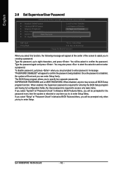
...GA-VM800PMC Motherboard - 42 - To disable password, just press when you to specify two separate passwords: SUPERVISOR PASSWORD and a USER PASSWORD. Once the password is rebooted or any time you can enter Setup freely. A message "PASSWORD DISABLED" will appear to eight characters, and press . The BIOS..., the Supervisor password is required for the password every time the system is disabled, the system will be prompted for entering the BIOS Setup program and having full configuration fields, the User password is required to access only basic items. If you select "System" ...
...GA-VM800PMC Motherboard - 42 - To disable password, just press when you to specify two separate passwords: SUPERVISOR PASSWORD and a USER PASSWORD. Once the password is rebooted or any time you can enter Setup freely. A message "PASSWORD DISABLED" will appear to eight characters, and press . The BIOS..., the Supervisor password is required for the password every time the system is disabled, the system will be prompted for entering the BIOS Setup program and having full configuration fields, the User password is required to access only basic items. If you select "System" ...


