Manual
Page 22
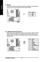
... from pins 5-6, 9-10. 10 9 2 1 Pin No. 1 2 3 4 5 6 7 8 9 10 Definition MIC GND MIC_BIAS POWER FrontAudio(R) Rear Audio (R)/ Return R NC No Pin FrontAudio (L) Rear Audio (L)/ Return L GA-VM800PMC Motherboard - 22 - Definition 1 MPD+ 1 2 MPD- 3 MPD- 10) F_AUDIO (Front Audio Panel Connector) Please make sure the pin assignment on the cable is on the MB... mode(S1). Pin No. English 9) PWR_LED The PWR_LED connector is connected with the system power indicator to use "Front Audio" connector, you are buying support front audio panel connector, please contact your dealer.
... from pins 5-6, 9-10. 10 9 2 1 Pin No. 1 2 3 4 5 6 7 8 9 10 Definition MIC GND MIC_BIAS POWER FrontAudio(R) Rear Audio (R)/ Return R NC No Pin FrontAudio (L) Rear Audio (L)/ Return L GA-VM800PMC Motherboard - 22 - Definition 1 MPD+ 1 2 MPD- 3 MPD- 10) F_AUDIO (Front Audio Panel Connector) Please make sure the pin assignment on the cable is on the MB... mode(S1). Pin No. English 9) PWR_LED The PWR_LED connector is connected with the system power indicator to use "Front Audio" connector, you are buying support front audio panel connector, please contact your dealer.

