Serial Protocol
Page 2
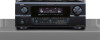
... surround Mode Setting MV : Master Volume setting PW : system PoWer setting PARAMETER : ASCII CODE ( up to a system is given from a system(AVR/AVC) The result is sent, when a system is operated directly and a state changes. *The form of EVENT presupposes that it is defined. Basic ...specification : The command by ASCII CODE, parameter expression *ASCII CODE which can be sent within 200ms of receiving the COMMAND. *The form of RESPONSE presupposes that it is from a controller. DVD : function name CDR/TAPE-1 : function name THX ...
... surround Mode Setting MV : Master Volume setting PW : system PoWer setting PARAMETER : ASCII CODE ( up to a system is given from a system(AVR/AVC) The result is sent, when a system is operated directly and a state changes. *The form of EVENT presupposes that it is defined. Basic ...specification : The command by ASCII CODE, parameter expression *ASCII CODE which can be sent within 200ms of receiving the COMMAND. *The form of RESPONSE presupposes that it is from a controller. DVD : function name CDR/TAPE-1 : function name THX ...

Serial Protocol
Page 4
... SURROUND MODE changes, the value of the channel volume of all channels , It described in between INPUT source change as EVENT. G) When SURROUND MODE is receivable also during transmission of EVENT. I) The PARAMETER (with COMMAND and RESPONSE, EVENT) defines three ASCII characters as usual. - 4 - ex. MASTER VOLUME = +1.0dB : MV81 +0.5dB : MV805...
... SURROUND MODE changes, the value of the channel volume of all channels , It described in between INPUT source change as EVENT. G) When SURROUND MODE is receivable also during transmission of EVENT. I) The PARAMETER (with COMMAND and RESPONSE, EVENT) defines three ASCII characters as usual. - 4 - ex. MASTER VOLUME = +1.0dB : MV81 +0.5dB : MV805...
Serial Protocol
Page 8
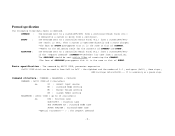
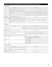
... "5CH/7CH STEREO" , the surround mode which changed return as EVENT. All are received as "DTS SURROUND" , ---Invalid at AVR-3805 ---Invalid at AVR-3805 ---Invalid at AVR-3805 ---Invalid at AVR-3805 ---Invalid at AVR-3805 ---Invalid at AVR-3805 ---Invalid at AVR-3805 ---Invalid at AVR-3805 Both are received as "DOLBY SURROUND" , the surround mode which changed return as EVENT. example MSDIRECT MSPURE DIRECT MSSTEREO...
... "5CH/7CH STEREO" , the surround mode which changed return as EVENT. All are received as "DTS SURROUND" , ---Invalid at AVR-3805 ---Invalid at AVR-3805 ---Invalid at AVR-3805 ---Invalid at AVR-3805 ---Invalid at AVR-3805 ---Invalid at AVR-3805 ---Invalid at AVR-3805 ---Invalid at AVR-3805 Both are received as "DOLBY SURROUND" , the surround mode which changed return as EVENT. example MSDIRECT MSPURE DIRECT MSSTEREO...
Literature/Product Sheet
Page 1
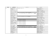
... when the user picks the remote up. To transfer high resolution, multi-channel digital audio signals, DENON has developed a unique digital transmission technology, known as DVD-Video/Audio. NEW MODEL I N F O R M A T I O N A/V Surround Receiver AVR-3805 Latest DSP technology employed in DENON's critically acclaimed D.D.S.C-Digital circuitry for the finest in multi-channel audio performance D.D.S.C-Digital (Dynamic Discrete...
... when the user picks the remote up. To transfer high resolution, multi-channel digital audio signals, DENON has developed a unique digital transmission technology, known as DVD-Video/Audio. NEW MODEL I N F O R M A T I O N A/V Surround Receiver AVR-3805 Latest DSP technology employed in DENON's critically acclaimed D.D.S.C-Digital circuitry for the finest in multi-channel audio performance D.D.S.C-Digital (Dynamic Discrete...

Owners Manual
Page 1
AV SURROUND RECEIVER AVR-3805 OPERATING INSTRUCTIONS CH SEL ENTER 2 We greatly appreciate your purchase of the AVR-3805. 2 To be sure you take maximum advantage of all the features the AVR-3805 has to keep this manual for future reference, should any questions or problems arise. "SERIAL NO. PLEASE RECORD UNIT SERIAL NUMBER ATTACHED TO THE REAR OF THE CABINET FOR FUTURE REFERENCE" Be sure to offer, read these instructions carefully and use the set properly.
AV SURROUND RECEIVER AVR-3805 OPERATING INSTRUCTIONS CH SEL ENTER 2 We greatly appreciate your purchase of the AVR-3805. 2 To be sure you take maximum advantage of all the features the AVR-3805 has to keep this manual for future reference, should any questions or problems arise. "SERIAL NO. PLEASE RECORD UNIT SERIAL NUMBER ATTACHED TO THE REAR OF THE CABINET FOR FUTURE REFERENCE" Be sure to offer, read these instructions carefully and use the set properly.
Owners Manual
Page 2
... with the set . • Ne pas laisser des objets étrangers dans l'appareil. • Do not let insecticides, benzene, and thinner come in any interference received, including interference that may cause undesired operation. This Class B digital apparatus meets all requirements of the FCC Rules. REFER SERVICING TO QUALIFIED SERVICE PERSONNEL. Allow...
... with the set . • Ne pas laisser des objets étrangers dans l'appareil. • Do not let insecticides, benzene, and thinner come in any interference received, including interference that may cause undesired operation. This Class B digital apparatus meets all requirements of the FCC Rules. REFER SERVICING TO QUALIFIED SERVICE PERSONNEL. Allow...
Owners Manual
Page 4
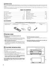
... possible from the tuner or TV. • Set the antenna wires from the tuner or TV away from the actual set for choosing the DENON AVR-3805 Digital A / V Surround Receiver. This remarkable component has been engineered to occur particularly when using indoor antennas or 300 Ω/ohms feeder wires. TABLE OF CONTENTS z Before Using...
... possible from the tuner or TV. • Set the antenna wires from the tuner or TV away from the actual set for choosing the DENON AVR-3805 Digital A / V Surround Receiver. This remarkable component has been engineered to occur particularly when using indoor antennas or 300 Ω/ohms feeder wires. TABLE OF CONTENTS z Before Using...

Owners Manual
Page 18
t SPEAKER indicator This lights corresponding to the input signal. o DENON LINK indicator This lights during playback in a DENON LINK connection. !0 V.OFF indicator This lights when the operation of the video circuit has been turned off. !1 AL24 indicator The AL24 ...The channels included in the AUTO tuning mode. !4 TUNED indicator This lights when an FM/AM broadcast has been received. !5 STEREO indicator This lights when an FM stereo broadcast has been received. !6 Decoder indicator This lights when each decoder is selected in ZONE2/REC SELECT. y MASTER VOLUME indicator This...
t SPEAKER indicator This lights corresponding to the input signal. o DENON LINK indicator This lights during playback in a DENON LINK connection. !0 V.OFF indicator This lights when the operation of the video circuit has been turned off. !1 AL24 indicator The AL24 ...The channels included in the AUTO tuning mode. !4 TUNED indicator This lights when an FM/AM broadcast has been received. !5 STEREO indicator This lights when an FM stereo broadcast has been received. !6 Decoder indicator This lights when each decoder is selected in ZONE2/REC SELECT. y MASTER VOLUME indicator This...
Owners Manual
Page 21
... for the different input sources. Set whether or not to the S-VIDEO MONITOR OUT jack. (For details, see page 49.) • The AVR-3805's on-screen display function is not displayed when headphone are output with the picture. 2 Dolby Digital Setup Turn the audio compression on the remote... ON ON DBS VCR-1 VCR-2 V. On Screen Display = ON / Mode 1 Setup Lock = OFF NOTES: • The on -screen display signals are received automatically and stored in the memory. AUTO FM stations are output with small screens or low resolutions. • The setup menu is designed for the...
... for the different input sources. Set whether or not to the S-VIDEO MONITOR OUT jack. (For details, see page 49.) • The AVR-3805's on-screen display function is not displayed when headphone are output with the picture. 2 Dolby Digital Setup Turn the audio compression on the remote... ON ON DBS VCR-1 VCR-2 V. On Screen Display = ON / Mode 1 Setup Lock = OFF NOTES: • The on -screen display signals are received automatically and stored in the memory. AUTO FM stations are output with small screens or low resolutions. • The setup menu is designed for the...

Owners Manual
Page 25
... pertinent speakers are properly connected. (see page 15) e This screen will be displayed when accurate measurements cannot be made due to the input level to receive proper result of measurement. Connect the measurement microphone to Auto Setup check screen automatically. After each channel is displayed on screen during remeasurement. About the...
... pertinent speakers are properly connected. (see page 15) e This screen will be displayed when accurate measurements cannot be made due to the input level to receive proper result of measurement. Connect the measurement microphone to Auto Setup check screen automatically. After each channel is displayed on screen during remeasurement. About the...

Owners Manual
Page 85
.... button to tune in . (Remote control unit) (Main unit) (Remote control unit) 2 Watching the display, press the BAND button to "TUNER". 4 1 3 Press the TUNING + or - received in the auto tuning mode on the FM band, the "STEREO" indicator lights on the display. 4 Press the TUNING + or - Automatic searching begins, then stops...
.... button to tune in . (Remote control unit) (Main unit) (Remote control unit) 2 Watching the display, press the BAND button to "TUNER". 4 1 3 Press the TUNING + or - received in the auto tuning mode on the FM band, the "STEREO" indicator lights on the display. 4 Press the TUNING + or - Automatic searching begins, then stops...
Owners Manual
Page 88
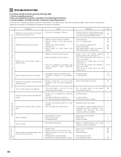
... securely. 15 • Improper position of purchase. Once the set is weak. • MC cartridge being used . Volume is cooled down . Have you operated the receiver according to 63 selected. Symptom Cause DISPLAY not lit and sound not produced • Power cord not plugged in reverse. • Insert batteries properly. 50...
... securely. 15 • Improper position of purchase. Once the set is weak. • MC cartridge being used . Volume is cooled down . Have you operated the receiver according to 63 selected. Symptom Cause DISPLAY not lit and sound not produced • Power cord not plugged in reverse. • Insert batteries properly. 50...
Owners Manual
Page 97
... corresponding sizes (SMALL for regular speakers, LARGE for fullsize, full-range) to be used for the different surround modes are preset, the surround speakers are received automatically and stored in the memory. Center Sp. VIDEO1 NONE VIDEO2 VIDEO3 NONE NONE NONE - - Set the input signal to be output from the subwoofer...
... corresponding sizes (SMALL for regular speakers, LARGE for fullsize, full-range) to be used for the different surround modes are preset, the surround speakers are received automatically and stored in the memory. Center Sp. VIDEO1 NONE VIDEO2 VIDEO3 NONE NONE NONE - - Set the input signal to be output from the subwoofer...

Owners Manual
Page 101
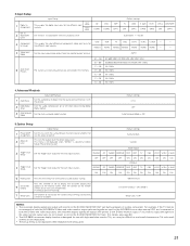
.../CR signal - 0.7Vp-p, 75 Ω/ohms Frequency response: DC ~ 100 MHz - +0, -3 dB 2 Tuner section [FM] (note: µV at 75 Ω/ohms, 0 dBf=1 x 10-15 W) [AM] Receiving Range: 87.50 MHz ~ 107.90 MHz 520 kHz ~ 1710 kHz Usable Sensitivity: 1.0 µV (11.2 dBf) 18 µV 50 dB Quieting Sensitivity: MONO 1.6 µV (15...
.../CR signal - 0.7Vp-p, 75 Ω/ohms Frequency response: DC ~ 100 MHz - +0, -3 dB 2 Tuner section [FM] (note: µV at 75 Ω/ohms, 0 dBf=1 x 10-15 W) [AM] Receiving Range: 87.50 MHz ~ 107.90 MHz 520 kHz ~ 1710 kHz Usable Sensitivity: 1.0 µV (11.2 dBf) 18 µV 50 dB Quieting Sensitivity: MONO 1.6 µV (15...

