Auto Setup Room EQ Features
Page 1
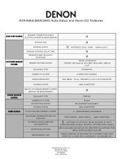
NORMAL (flat response up to 2kHz, above 2kHz -3dB/oct) - C. AVR-985S/2805/3805 Auto-Setup and Room EQ Features AUTO SETUP FEATURES SPEAKER CONNECTION CHECK (FL/C/FR/SL [A+B]/SR [A+B]/SBL/SBR/SW) AUTO ROOM EQUALIZER FEATURES SPEAKER SIZE SPEAKER LEVELS SPEAKER ...PARTY MICROPHONE THAT MEETS SUPPLIED SPECIFICATIONS UNDER 3 MINUTES, 30 SECONDS FOR 10 CHANNEL ANALYZING FRONT L/R, C, SL/SR (BOTH SURROUND A + B), SBL/SBR, SW DENON Electronics (USA), LLC 19 Chapin Rd., Bldg. FLAT PARAMETRIC NUMBER OF FILTERS 8 BANDS PER CHANNEL CENTER FREQUENCY 40Hz-18KHz, 1/3 oct., SPEAKER Q: 0.2-2.0: AUTO...
NORMAL (flat response up to 2kHz, above 2kHz -3dB/oct) - C. AVR-985S/2805/3805 Auto-Setup and Room EQ Features AUTO SETUP FEATURES SPEAKER CONNECTION CHECK (FL/C/FR/SL [A+B]/SR [A+B]/SBL/SBR/SW) AUTO ROOM EQUALIZER FEATURES SPEAKER SIZE SPEAKER LEVELS SPEAKER ...PARTY MICROPHONE THAT MEETS SUPPLIED SPECIFICATIONS UNDER 3 MINUTES, 30 SECONDS FOR 10 CHANNEL ANALYZING FRONT L/R, C, SL/SR (BOTH SURROUND A + B), SBL/SBR, SW DENON Electronics (USA), LLC 19 Chapin Rd., Bldg. FLAT PARAMETRIC NUMBER OF FILTERS 8 BANDS PER CHANNEL CENTER FREQUENCY 40Hz-18KHz, 1/3 oct., SPEAKER Q: 0.2-2.0: AUTO...
Auto Setup Specifications
Page 1
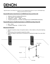
Specifications and Setup Procedure for Non-DENON Microphone Use for AVR-3805 Auto Setup and Room EQ Function Required Microphone Specifications for DENON Auto-Setup and Room EQ • ...Element : Electric Condenser Microphone • Polar Pattern : Omni-directional • Sensitivity : -40 dBV (0dB = 1V/1Pa) • Frequency Response : 20-20kHz Flat Response (Ex: BEHRINGER ECM-8000) Required Microphone Amplifier Specification for DENON Auto-Setup...
Specifications and Setup Procedure for Non-DENON Microphone Use for AVR-3805 Auto Setup and Room EQ Function Required Microphone Specifications for DENON Auto-Setup and Room EQ • ...Element : Electric Condenser Microphone • Polar Pattern : Omni-directional • Sensitivity : -40 dBV (0dB = 1V/1Pa) • Frequency Response : 20-20kHz Flat Response (Ex: BEHRINGER ECM-8000) Required Microphone Amplifier Specification for DENON Auto-Setup...
Auto Setup Specifications
Page 3
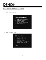
Channel Level" 3 D E N O N E L E C T R O N I C S ( U S A ), LLC. Speaker Setup" • Select "3. Push the "SYSTEM SETUP" button on AVR-3805 • Select "2.
Channel Level" 3 D E N O N E L E C T R O N I C S ( U S A ), LLC. Speaker Setup" • Select "3. Push the "SYSTEM SETUP" button on AVR-3805 • Select "2.

Auto Setup Specifications
Page 4
... • Adjust the "microphone amplifier's gain" as the RMS Volt Meter becomes about 120[mV RMS] • Once set, exit out of 'System Setup' and turn off the AVR-3805 4 You do not have to check any of the other channels. • Adjust the "Main Volume" so that the Sound Pressure Level measures...
... • Adjust the "microphone amplifier's gain" as the RMS Volt Meter becomes about 120[mV RMS] • Once set, exit out of 'System Setup' and turn off the AVR-3805 4 You do not have to check any of the other channels. • Adjust the "Main Volume" so that the Sound Pressure Level measures...
Auto Setup Specifications
Page 5
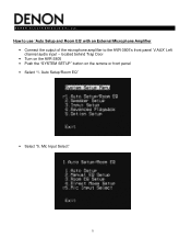
located behind Trap Door • Turn on the AVR-3805 • Push the "SYSTEM SETUP" button on the remote or front panel • Select "1. Auto Setup/Room EQ" • Select "5. How to use 'Auto Setup and Room EQ' with an External Microphone Amplifier • Connect the output of the microphone amplifier to the AVR-3805's front panel 'V.AUX' Left channel audio input - Mic Input Select" 5 D E N O N E L E C T R O N I C S ( U S A ), LLC.
located behind Trap Door • Turn on the AVR-3805 • Push the "SYSTEM SETUP" button on the remote or front panel • Select "1. Auto Setup/Room EQ" • Select "5. How to use 'Auto Setup and Room EQ' with an External Microphone Amplifier • Connect the output of the microphone amplifier to the AVR-3805's front panel 'V.AUX' Left channel audio input - Mic Input Select" 5 D E N O N E L E C T R O N I C S ( U S A ), LLC.
Auto Setup Specifications
Page 6
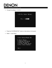
Auto Setup" 6 D E N O N E L E C T R O N I C S ( U S A ), LLC. • Change the setting to "V.AUX L" • Press the "SYSTEM SETUP" button on the remote or front panel • Select "1.
Auto Setup" 6 D E N O N E L E C T R O N I C S ( U S A ), LLC. • Change the setting to "V.AUX L" • Press the "SYSTEM SETUP" button on the remote or front panel • Select "1.

Auto Setup Specifications
Page 7
D E N O N E L E C T R O N I C S ( U S A ), LLC. • Start "Auto-Setup" Once Auto Setup and Room EQ has completed, please continue with 'System Setup' as described in the Owner's Manual. 7
D E N O N E L E C T R O N I C S ( U S A ), LLC. • Start "Auto-Setup" Once Auto Setup and Room EQ has completed, please continue with 'System Setup' as described in the Owner's Manual. 7
Literature/Product Sheet
Page 1
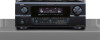
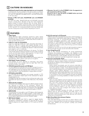
... equipped with an Auto Setup and Room Equalization function, to ensure a rock stable supply of power. • Detachable AC Power Cord The AVR-3805 incorporates this latest digital audio interface, so the end user will turn off any unneeded circuitry of the AVR-3805. • When listening to PCM based sources, DENON's waveform technology AL24 Processing...
... equipped with an Auto Setup and Room Equalization function, to ensure a rock stable supply of power. • Detachable AC Power Cord The AVR-3805 incorporates this latest digital audio interface, so the end user will turn off any unneeded circuitry of the AVR-3805. • When listening to PCM based sources, DENON's waveform technology AL24 Processing...
Owners Manual
Page 5
...of Dolby Pro Logic II to the previously offered Music and Cinema modes, the AVR-3805 also offers a Game mode optimum for DVD and North American DTV. 2. Auto setup requires an optional microphone for setup use the surround channel(s) to the input jacks. Producers of multi-channel discrete ... of PRE OUT jacks, HEADPHONE jack and SPEAKER terminals The PRE OUT jacks, HEADPHONE jack and SPEAKER terminals include a muting circuit. The DENON AVR-3805 provides the ability to be enjoyed in the STANDBY state, the apparatus is the default digital audio delivery system for games. 4. If this...
...of Dolby Pro Logic II to the previously offered Music and Cinema modes, the AVR-3805 also offers a Game mode optimum for DVD and North American DTV. 2. Auto setup requires an optional microphone for setup use the surround channel(s) to the input jacks. Producers of multi-channel discrete ... of PRE OUT jacks, HEADPHONE jack and SPEAKER terminals The PRE OUT jacks, HEADPHONE jack and SPEAKER terminals include a muting circuit. The DENON AVR-3805 provides the ability to be enjoyed in the STANDBY state, the apparatus is the default digital audio delivery system for games. 4. If this...
Owners Manual
Page 7
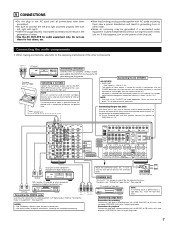
... RL DIGITAL AUDIO Connecting a CD player Connect the CD player's analog output jacks (ANALOG OUTPUT) to the right jack. For details, see "Setting the Trigger Setup". (See page 46) CD recorder or Tape deck B NOTE: If humming noise is above 120 W (1 A.).
... RL DIGITAL AUDIO Connecting a CD player Connect the CD player's analog output jacks (ANALOG OUTPUT) to the right jack. For details, see "Setting the Trigger Setup". (See page 46) CD recorder or Tape deck B NOTE: If humming noise is above 120 W (1 A.).
Owners Manual
Page 10
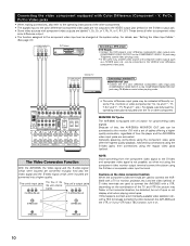
...TVs, monitors or video components ("CR, CB and Y", "RY, B-Y and Y", "Pr, Pb and Y", etc.). The Video Conversion Function With the AVR-3805, the Video signal and the S-video signal which were inputted are converted mutually. Because of this unit's internal signals. (Color Diffrence Video jack) (Color... monitor (TV) with a VTR, depending on the combination of the TV and VTR the picture may be changed at the system setup. Generally speaking, connections using the component video jacks offer the highest quality playback, followed by connections using the S-Video jacks, then connections...
...TVs, monitors or video components ("CR, CB and Y", "RY, B-Y and Y", "Pr, Pb and Y", etc.). The Video Conversion Function With the AVR-3805, the Video signal and the S-video signal which were inputted are converted mutually. Because of this unit's internal signals. (Color Diffrence Video jack) (Color... monitor (TV) with a VTR, depending on the combination of the TV and VTR the picture may be changed at the system setup. Generally speaking, connections using the component video jacks offer the highest quality playback, followed by connections using the S-Video jacks, then connections...
Owners Manual
Page 13
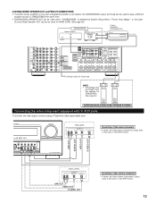
... video component equipped with V. [3] ZONE2/ZONE3 SPEAKER OUT and PREOUT CONNECTIONS • If another power amplifier or pre-main (integrated) amplifier is selected at System Setup Menu "Power Amp Assign". AUX INPUT jacks. 13 Video game OUTPUT R L OPTICAL VIDEO OUT S-VIDEO OUT RL Connecting a Video game component • Connect the Video...
... video component equipped with V. [3] ZONE2/ZONE3 SPEAKER OUT and PREOUT CONNECTIONS • If another power amplifier or pre-main (integrated) amplifier is selected at System Setup Menu "Power Amp Assign". AUX INPUT jacks. 13 Video game OUTPUT R L OPTICAL VIDEO OUT S-VIDEO OUT RL Connecting a Video game component • Connect the Video...
Owners Manual
Page 14
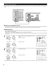
... CH SEL ENTER Select the digital input jack to be transferred by DENON LINK. • When the input mode is possible by connecting the AVR-3805 to a Denon DVD player equipped with a DENON LINK connector using the DENON Link connector Digital transfer and multi-channel playback of DVD audio discs and...Player. 2 Playback using the connection cable included with the DVD player. 2 DENON LINK Setting When a DENON DVD player and the DENON LINK have been connected, be sure to make a setting to "DENON LINK" with the System Setup Digital In Assignment. (See page 39) • Select the input for ...
... CH SEL ENTER Select the digital input jack to be transferred by DENON LINK. • When the input mode is possible by connecting the AVR-3805 to a Denon DVD player equipped with a DENON LINK connector using the DENON Link connector Digital transfer and multi-channel playback of DVD audio discs and...Player. 2 Playback using the connection cable included with the DVD player. 2 DENON LINK Setting When a DENON DVD player and the DENON LINK have been connected, be sure to make a setting to "DENON LINK" with the System Setup Digital In Assignment. (See page 39) • Select the input for ...

Owners Manual
Page 17
IN button 63, 65) u SYSTEM SETUP button 22, 49, 78) i CURSOR button o CH SELECT/ENTER button !0 SURROUND BACK button 76) !1 V.AUX input jacks 13) !2 PURE DIRECT button 66) !3 DIRECT button 66) !4 ... button 80, 81) !8 SURROUND PARAMETER button 74 ~ 78) !9 TONE CONTROL button 67, 82, 83) @0 TONE DEFEAT button 67) @1 STATUS button 68) @2 ROOM EQ button 28) @3 SETUP MIC jack 23) @4 MASTER VOLUME control 64) @5 MASTER VOLUME indicator 64) @6 Display @7 Remote control sensor (REMOTE SENSOR 50) @8 FUNCTION knob 63, 67, 68, 71, 87...
IN button 63, 65) u SYSTEM SETUP button 22, 49, 78) i CURSOR button o CH SELECT/ENTER button !0 SURROUND BACK button 76) !1 V.AUX input jacks 13) !2 PURE DIRECT button 66) !3 DIRECT button 66) !4 ... button 80, 81) !8 SURROUND PARAMETER button 74 ~ 78) !9 TONE CONTROL button 67, 82, 83) @0 TONE DEFEAT button 67) @1 STATUS button 68) @2 ROOM EQ button 28) @3 SETUP MIC jack 23) @4 MASTER VOLUME control 64) @5 MASTER VOLUME indicator 64) @6 Display @7 Remote control sensor (REMOTE SENSOR 50) @8 FUNCTION knob 63, 67, 68, 71, 87...

Owners Manual
Page 18
r Output signal channel indicator The audio channels output from this unit will light. The Setup item number is selected in System Setup. y MASTER VOLUME indicator This displays the volume level. u MULTI(ZONE) indicator ZONE2 mode is displayed in ZONE2/REC SELECT. w ...e Information display This displays the surround mode, function name or setting value, etc. REC OUT mode is operating. 18 o DENON LINK indicator This lights during playback in a DENON LINK connection. !0 V.OFF indicator This lights when the operation of the video circuit has been turned off. !1 AL24 indicator ...
r Output signal channel indicator The audio channels output from this unit will light. The Setup item number is selected in System Setup. y MASTER VOLUME indicator This displays the volume level. u MULTI(ZONE) indicator ZONE2 mode is displayed in ZONE2/REC SELECT. w ...e Information display This displays the surround mode, function name or setting value, etc. REC OUT mode is operating. 18 o DENON LINK indicator This lights during playback in a DENON LINK connection. !0 V.OFF indicator This lights when the operation of the video circuit has been turned off. !1 AL24 indicator ...

Owners Manual
Page 19
..., 71) Mode selector buttons 20, 51, 54, 62) Input source button 51, 62) Surround mode button.........(51, 62, 66, 73) SYSTEM buttons 51 ~ 55) SYSTEM SETUP button 20, 49) ROOM EQ button 28) Tuner system buttons ..........(52, 59, 71, 85) VIDEO ON/OFF button 66) INPUT MODE selector buttons 63) Remote...
..., 71) Mode selector buttons 20, 51, 54, 62) Input source button 51, 62) Surround mode button.........(51, 62, 66, 73) SYSTEM buttons 51 ~ 55) SYSTEM SETUP button 20, 49) ROOM EQ button 28) Tuner system buttons ..........(52, 59, 71, 85) VIDEO ON/OFF button 66) INPUT MODE selector buttons 63) Remote...
Owners Manual
Page 20
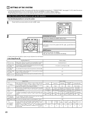
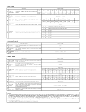
... use for zone2 or zone3. 2 Manual EQ Setup This parameter is for optimizing the Room EQ with which the bass so of the various speaker is in Direct or Pure Direct. 5 Mic Input Select Set this function when using the AVR-3805's on the screen ENTER button Press this button ...to complete the setting. • System setup items and default values (set the composition of the signals output from the speakers and the frequency ...
... use for zone2 or zone3. 2 Manual EQ Setup This parameter is for optimizing the Room EQ with which the bass so of the various speaker is in Direct or Pure Direct. 5 Mic Input Select Set this function when using the AVR-3805's on the screen ENTER button Press this button ...to complete the setting. • System setup items and default values (set the composition of the signals output from the speakers and the frequency ...
Owners Manual
Page 21
... to the S-Video monitor output. On Screen Display = ON / Mode 1 Setup Lock = OFF NOTES: • The on -screen display that they cannot be difficult to read small characters on TVs with priority to both the AVR-3805's S-Video and video monitor output jacks and signals are operated. In Subwoofer terminal... a cord to the S-VIDEO MONITOR OUT jack. (For details, see page 49.) • The AVR-3805's on the remote control unit or main unit are input to lock the system setup settings so that appears on the monitor screen when the controls on -screen display function is designed for...
... to the S-Video monitor output. On Screen Display = ON / Mode 1 Setup Lock = OFF NOTES: • The on -screen display that they cannot be difficult to read small characters on TVs with priority to both the AVR-3805's S-Video and video monitor output jacks and signals are operated. In Subwoofer terminal... a cord to the S-VIDEO MONITOR OUT jack. (For details, see page 49.) • The AVR-3805's on the remote control unit or main unit are input to lock the system setup settings so that appears on the monitor screen when the controls on -screen display function is designed for...
Owners Manual
Page 22
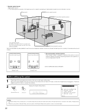
... large table title as contained in the tables of Pages 20 and 21. • Wherever your position in . Surround speaker systems With the AVR-3805 it is also possible to use the surround speaker selector function to choose the best layout for a variety of sources and surround modes. •... not be possible when the unit is of a layered design that all the connections are plugged in System Setup, one more press of the System Setup button permits a move to achieve the optimum sound fields for a system consisting of eight speaker systems and a television monitor: Subwoofer Center speaker...
... large table title as contained in the tables of Pages 20 and 21. • Wherever your position in . Surround speaker systems With the AVR-3805 it is also possible to use the surround speaker selector function to choose the best layout for a variety of sources and surround modes. •... not be possible when the unit is of a layered design that all the connections are plugged in System Setup, one more press of the System Setup button permits a move to achieve the optimum sound fields for a system consisting of eight speaker systems and a television monitor: Subwoofer Center speaker...
Owners Manual
Page 23
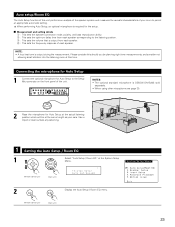
...optimum delay time from each speaker. e : This sets the volume that is DENON DM-S305 sold separately. • When using other microphone see page 30. 2 Place the microphone for Auto Setup at the actual listening position which will be planning night time measurements, and consider...CH SEL ENTER NOTES: • The optional standard microphone is output from each speaker. Connecting the microphone for Auto Setup 1 Connect the optional microphone for the setup. 2 Measurement and setting details q : This sets the speaker connection mode, polarity, and bass reproduction ability. Use ...
...optimum delay time from each speaker. e : This sets the volume that is DENON DM-S305 sold separately. • When using other microphone see page 30. 2 Place the microphone for Auto Setup at the actual listening position which will be planning night time measurements, and consider...CH SEL ENTER NOTES: • The optional standard microphone is output from each speaker. Connecting the microphone for Auto Setup 1 Connect the optional microphone for the setup. 2 Measurement and setting details q : This sets the speaker connection mode, polarity, and bass reproduction ability. Use ...


