Auto Setup Room EQ Features
Page 1
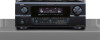
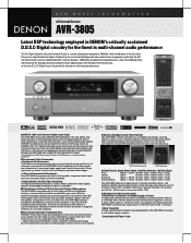
... Brook, NJ. 07058 973-396-0810 www.usa.denon.com AVR-985S/2805/3805 Auto-Setup and Room EQ Features AUTO SETUP FEATURES SPEAKER CONNECTION CHECK (FL/C/FR/SL [A+B]/SR [A+B]/SBL/SBR/SW) AUTO ROOM EQUALIZER FEATURES SPEAKER SIZE SPEAKER LEVELS SPEAKER DISTANCE (DELAY TIME) SPEAKER PHASE (POLARITY) DETECTION MEMORY SETTING CURVES EQUALIZER TYPE þ þ þ REFERENCE...
... Brook, NJ. 07058 973-396-0810 www.usa.denon.com AVR-985S/2805/3805 Auto-Setup and Room EQ Features AUTO SETUP FEATURES SPEAKER CONNECTION CHECK (FL/C/FR/SL [A+B]/SR [A+B]/SBL/SBR/SW) AUTO ROOM EQUALIZER FEATURES SPEAKER SIZE SPEAKER LEVELS SPEAKER DISTANCE (DELAY TIME) SPEAKER PHASE (POLARITY) DETECTION MEMORY SETTING CURVES EQUALIZER TYPE þ þ þ REFERENCE...
Auto Setup Specifications
Page 2
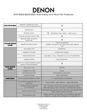
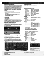
... the Sound Pressure Level with the microphone amplifier • Turn on the AVR-3805 and the "microphone amplifier" • Turn on the "Phantom Supply" on -screen display) with the AVR-3805 • Connect the microphone with SPL meter at the Microphone point. Adjust AVR volume SPL meter = 80dB(c) Microphone MIC AMP with mic power supply... to 120m V rms using Sound Level Meter and RMS Volt Meter First you will need to adjust the "microphone amplifier gain". • Connect all the speakers and the video monitor (for the on the microphone amplifier AVR3805...
... the Sound Pressure Level with the microphone amplifier • Turn on the AVR-3805 and the "microphone amplifier" • Turn on the "Phantom Supply" on -screen display) with the AVR-3805 • Connect the microphone with SPL meter at the Microphone point. Adjust AVR volume SPL meter = 80dB(c) Microphone MIC AMP with mic power supply... to 120m V rms using Sound Level Meter and RMS Volt Meter First you will need to adjust the "microphone amplifier gain". • Connect all the speakers and the video monitor (for the on the microphone amplifier AVR3805...
Auto Setup Specifications
Page 3
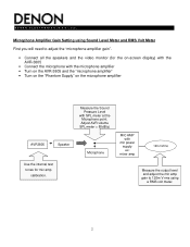
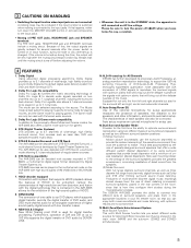
Speaker Setup" • Select "3. Channel Level" 3 D E N O N E L E C T R O N I C S ( U S A ), LLC. Push the "SYSTEM SETUP" button on AVR-3805 • Select "2.
Speaker Setup" • Select "3. Channel Level" 3 D E N O N E L E C T R O N I C S ( U S A ), LLC. Push the "SYSTEM SETUP" button on AVR-3805 • Select "2.

Auto Setup Specifications
Page 4
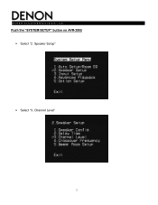
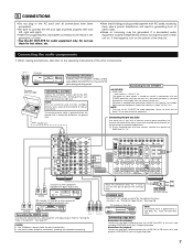
...) • Once the 'Main Volume" as been set , exit out of microphone amplifier to 'Yes' • Once the test tone for the Front Left (FL) speaker starts, check the Sound Pressure Level at the Listening Point with an SPL Meter. D E N O N E L E C T R O N I C S ( U S A ), LLC. • Set the Parameter "Test Tone" to 'Manual' and "Test... amplifier's gain" as the RMS Volt Meter becomes about 120[mV RMS] • Once set , connect the output of 'System Setup' and turn off the AVR-3805 4
...) • Once the 'Main Volume" as been set , exit out of microphone amplifier to 'Yes' • Once the test tone for the Front Left (FL) speaker starts, check the Sound Pressure Level at the Listening Point with an SPL Meter. D E N O N E L E C T R O N I C S ( U S A ), LLC. • Set the Parameter "Test Tone" to 'Manual' and "Test... amplifier's gain" as the RMS Volt Meter becomes about 120[mV RMS] • Once set , connect the output of 'System Setup' and turn off the AVR-3805 4
Literature/Product Sheet
Page 1
...new 32bit floating point DSP automatically and accurately analyzes, adjusts and sets the speaker configurations of your room. NEW MODEL I N F O R M A T I O N A/V Surround Receiver AVR-3805 Latest DSP technology employed in DENON's critically acclaimed D.D.S.C-Digital circuitry for DVD players is currently awaiting verification. &#... high resolution, multi-channel digital audio signals, DENON has developed a unique digital transmission technology, known as DVD-Video/Audio. Also, the AVR-3805 analyzes and adjusts the frequency response of the speakers to the room with Analog Devices, a new...
...new 32bit floating point DSP automatically and accurately analyzes, adjusts and sets the speaker configurations of your room. NEW MODEL I N F O R M A T I O N A/V Surround Receiver AVR-3805 Latest DSP technology employed in DENON's critically acclaimed D.D.S.C-Digital circuitry for DVD players is currently awaiting verification. &#... high resolution, multi-channel digital audio signals, DENON has developed a unique digital transmission technology, known as DVD-Video/Audio. Also, the AVR-3805 analyzes and adjusts the frequency response of the speakers to the room with Analog Devices, a new...
Literature/Product Sheet
Page 2
... BACK L/R, SUBWOOFER 5 Digital (Optical) Input OPTICAL x 5 (FRONT x 1) (Assignable) 2 Digital (Coaxial) Input COAXIAL x 2 (Assignable) 1 Denon Link Denon Link (Assignable) ■ Audio Outputs 8 Analog PRE Output FRONT L/R, CENTER, SURROUND L/R, SURROUND BACK L/R, SUBWOOFER 3 Analog REC Output VCR-1, VCR-2, ...M A T I O N AVR-3805 ■ Support for Multi Zone Configurations • The AVR-3805 provides a Multi Zone Output function and a Select function that let you more accurately match the performance characteristics of the subwoofer to the main speaker system. • A/B switching ...
... BACK L/R, SUBWOOFER 5 Digital (Optical) Input OPTICAL x 5 (FRONT x 1) (Assignable) 2 Digital (Coaxial) Input COAXIAL x 2 (Assignable) 1 Denon Link Denon Link (Assignable) ■ Audio Outputs 8 Analog PRE Output FRONT L/R, CENTER, SURROUND L/R, SURROUND BACK L/R, SUBWOOFER 3 Analog REC Output VCR-1, VCR-2, ...M A T I O N AVR-3805 ■ Support for Multi Zone Configurations • The AVR-3805 provides a Multi Zone Output function and a Select function that let you more accurately match the performance characteristics of the subwoofer to the main speaker system. • A/B switching ...
Owners Manual
Page 5
...be sure to the input jacks. Auto setup requires an optional microphone for setup use of direct radiating (monopolar) surround speakers, placed in the AVR-3805 allows for listening Different sources can be played in up to 7.1 channels. HDCD decoder equipped Connection with a player that..., including the surround back channel. DTS (Digital Theater Systems) DTS provides up during the mixing/creation process. The DENON AVR-3805 provides the ability to connect two different sets of PRE OUT jacks, HEADPHONE jack and SPEAKER terminals The PRE OUT jacks, HEADPHONE jack and...
...be sure to the input jacks. Auto setup requires an optional microphone for setup use of direct radiating (monopolar) surround speakers, placed in the AVR-3805 allows for listening Different sources can be played in up to 7.1 channels. HDCD decoder equipped Connection with a player that..., including the surround back channel. DTS (Digital Theater Systems) DTS provides up during the mixing/creation process. The DENON AVR-3805 provides the ability to connect two different sets of PRE OUT jacks, HEADPHONE jack and SPEAKER terminals The PRE OUT jacks, HEADPHONE jack and...
Owners Manual
Page 7
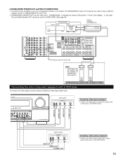
... and surround sound channels, or for connection to these outlets is used with digital output. Route the connection cords, etc., in conjunction with one speaker, connect the speaker to the operating instructions of this unit's CD jacks using pin plug cords. If humming or other noise. • Noise or humming may be...
... and surround sound channels, or for connection to these outlets is used with digital output. Route the connection cords, etc., in conjunction with one speaker, connect the speaker to the operating instructions of this unit's CD jacks using pin plug cords. If humming or other noise. • Noise or humming may be...
Owners Manual
Page 13
...OUT S-VIDEO OUT RL Connecting a Video game component • Connect the Video game component's output jacks to use this speaker for future use. In this case , Surround Back Speaker OUT cannot be changed to this unit's V. NOTE: • The settings must be used for MAIN ZONE. (See ...INPUT + + RC-616 INFRARED RETRANSMITTER AUX OUT L R Extension jacks for ZONE2/ZONE3. (See page 45.) (L) (R) SURROUND BACK/ZONE2/ZONE3 SPEAKER SYSTEMS Connecting the video component equipped with V. AUX INPUT jacks. 13 AUX INPUT jacks. LINE OUT DIGITAL OUT VIDEO OUT S-VIDEO OUT CH SEL...
...OUT S-VIDEO OUT RL Connecting a Video game component • Connect the Video game component's output jacks to use this speaker for future use. In this case , Surround Back Speaker OUT cannot be changed to this unit's V. NOTE: • The settings must be used for MAIN ZONE. (See ...INPUT + + RC-616 INFRARED RETRANSMITTER AUX OUT L R Extension jacks for ZONE2/ZONE3. (See page 45.) (L) (R) SURROUND BACK/ZONE2/ZONE3 SPEAKER SYSTEMS Connecting the video component equipped with V. AUX INPUT jacks. 13 AUX INPUT jacks. LINE OUT DIGITAL OUT VIDEO OUT S-VIDEO OUT CH SEL...

Owners Manual
Page 15
... the set is played for ZONE2/ZONE3. (L) (R) See page 45. SURROUND BACK/MULTI ZONE SPEAKER SYSTEMS (L) (R) SURROUND SPEAKER SYSTEMS (B) 15 NOTE: NEVER touch the speaker terminals when the power is placed near a TV or video monitor, the colors on . Tighten... , √ with √ ). Insert the cord. FRONT SPEAKER SYSTEMS CENTER SPEAKER SYSTEM SURROUND SPEAKER SYSTEMS (A) (L) (R) (L) (R) • Precautions when connecting speakers If a speaker is on the screen may be disturbed by the speaker's magnetism. Either tightly twist or terminate the core wires. Connection...
... the set is played for ZONE2/ZONE3. (L) (R) See page 45. SURROUND BACK/MULTI ZONE SPEAKER SYSTEMS (L) (R) SURROUND SPEAKER SYSTEMS (B) 15 NOTE: NEVER touch the speaker terminals when the power is placed near a TV or video monitor, the colors on . Tighten... , √ with √ ). Insert the cord. FRONT SPEAKER SYSTEMS CENTER SPEAKER SYSTEM SURROUND SPEAKER SYSTEMS (A) (L) (R) (L) (R) • Precautions when connecting speakers If a speaker is on the screen may be disturbed by the speaker's magnetism. Either tightly twist or terminate the core wires. Connection...
Owners Manual
Page 16
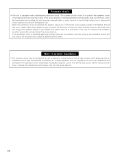
... cut off and the power supply indicator LED flashes. Turn off the set is cut off . If the protector circuit is activated, the speaker output is played for long periods of time at high output over a long period which results in an extreme temperature rise. Should this occur...of this circuit is to switch off the power and contact a DENON service center. Note on . Improve the ventilation condition around the unit and switch the power back on speaker impedance • The protector circuit may be sure to protect the speakers under circumstances such as when the output of the...
... cut off and the power supply indicator LED flashes. Turn off the set is cut off . If the protector circuit is activated, the speaker output is played for long periods of time at high output over a long period which results in an extreme temperature rise. Should this occur...of this circuit is to switch off the power and contact a DENON service center. Note on . Improve the ventilation condition around the unit and switch the power back on speaker impedance • The protector circuit may be sure to protect the speakers under circumstances such as when the output of the...

Owners Manual
Page 18
.... i REC OUT SOURCE indicator. w INPUT SIGNAL CHANNEL indicator The channels included in the input source will light. o DENON LINK indicator This lights during playback in a DENON LINK connection. !0 V.OFF indicator This lights when the operation of the video circuit has been turned off. !1 AL24 ... lights when an FM stereo broadcast has been received. !6 Decoder indicator This lights when each decoder is operating. 18 t SPEAKER indicator This lights corresponding to the settings of the surround speakers of the various surround modes. The Setup item number is displayed in System Setup.
.... i REC OUT SOURCE indicator. w INPUT SIGNAL CHANNEL indicator The channels included in the input source will light. o DENON LINK indicator This lights during playback in a DENON LINK connection. !0 V.OFF indicator This lights when the operation of the video circuit has been turned off. !1 AL24 ... lights when an FM stereo broadcast has been received. !6 Decoder indicator This lights when each decoder is operating. 18 t SPEAKER indicator This lights corresponding to the settings of the surround speakers of the various surround modes. The Setup item number is displayed in System Setup.

Owners Manual
Page 19
... buttons 20) Master volume control buttons 64, 71) CH SELECT/ENTER button ........(20, 72, 73) MUTING button 67) SYSTEM buttons 51 ~ 55) DIMMER button 68) SPEAKER button 68) TEST TONE button 72) 19 Remote control unit • For details on the functions of these parts, refer to the pages given in...
... buttons 20) Master volume control buttons 64, 71) CH SELECT/ENTER button ........(20, 72, 73) MUTING button 67) SYSTEM buttons 51 ~ 55) DIMMER button 68) SPEAKER button 68) TEST TONE button 72) 19 Remote control unit • For details on the functions of these parts, refer to the pages given in...
Owners Manual
Page 20
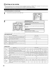
...Input jack for fullsize, full-range) to AMP mode. 2 SYSTEM SETUP button Press this function when using the AVR-3805's on the monitor screen using multiple surround speaker combinations for Mic or V.Aux Lchannel input jack. CURSOR buttons Use these to move the cursors the left, right...1 Check that the remote control unit set up the listening room's AV system centered around the AVR-3805. Default settings SURROUND BACK All Channel and Frequency=0dB All OFF Mic 2. Surround mode Surround speaker Front Sp. A / B Surround Back Sp. Use the following buttons to set up the ...
...Input jack for fullsize, full-range) to AMP mode. 2 SYSTEM SETUP button Press this function when using the AVR-3805's on the monitor screen using multiple surround speaker combinations for Mic or V.Aux Lchannel input jack. CURSOR buttons Use these to move the cursors the left, right...1 Check that the remote control unit set up the listening room's AV system centered around the AVR-3805. Default settings SURROUND BACK All Channel and Frequency=0dB All OFF Mic 2. Surround mode Surround speaker Front Sp. A / B Surround Back Sp. Use the following buttons to set up the ...
Owners Manual
Page 22
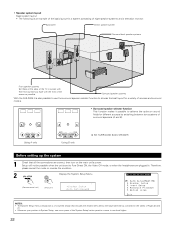
Surround speaker systems With the AVR-3805 it is also possible to use the surround speaker selector function to choose the best layout for a variety of sources and surround modes. • Surround speaker selector function This function makes it possible to Pure Direct ON, the Video Off mode, or ... • The following is an example of the basic layout for a system consisting of eight speaker systems and a television monitor: Subwoofer Center speaker system Surround back speaker systems Front speaker systems Set these at the sides of the TV or screen with their front surfaces as flush...
Surround speaker systems With the AVR-3805 it is also possible to use the surround speaker selector function to choose the best layout for a variety of sources and surround modes. • Surround speaker selector function This function makes it possible to Pure Direct ON, the Video Off mode, or ... • The following is an example of the basic layout for a system consisting of eight speaker systems and a television monitor: Subwoofer Center speaker system Surround back speaker systems Front speaker systems Set these at the sides of the TV or screen with their front surfaces as flush...
Owners Manual
Page 23
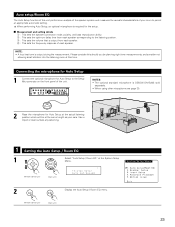
... (Remote control unit) (Main unit) Display the Auto Setup / Room EQ menu. 23 r : This sets the frequency response of each speaker corresponding to the listening position. CH SEL ENTER NOTES: • The optional standard microphone is required for the setup. 2 Measurement and setting... details q : This sets the speaker connection mode, polarity, and bass reproduction ability. When performing Auto Setup, an optional microphone is DENON DM-S305 sold separately. • When using other microphone see page 30. 2 Place the...
... (Remote control unit) (Main unit) Display the Auto Setup / Room EQ menu. 23 r : This sets the frequency response of each speaker corresponding to the listening position. CH SEL ENTER NOTES: • The optional standard microphone is required for the setup. 2 Measurement and setting... details q : This sets the speaker connection mode, polarity, and bass reproduction ability. When performing Auto Setup, an optional microphone is DENON DM-S305 sold separately. • When using other microphone see page 30. 2 Place the...

Owners Manual
Page 24
...When "ZONE2" or "ZONE3" is selected, change the setting to ZONE2 or ZONE3 (Another room). The results is reflected in "21.setting the type of speakers. 1-1 Setting the Auto Setup 1 CH SEL ENTER CH SEL ENTER (Remote control unit) (Main unit) Select "Auto Setup" at System Setup Menu "Power... Amp Assign", surround back speaker is not displayed as the target of setup in "5-1.Power Amp Assign". *Auto Setup Start w Press the Cursor left button. (Remote control unit) (Main...
...When "ZONE2" or "ZONE3" is selected, change the setting to ZONE2 or ZONE3 (Another room). The results is reflected in "21.setting the type of speakers. 1-1 Setting the Auto Setup 1 CH SEL ENTER CH SEL ENTER (Remote control unit) (Main unit) Select "Auto Setup" at System Setup Menu "Power... Amp Assign", surround back speaker is not displayed as the target of setup in "5-1.Power Amp Assign". *Auto Setup Start w Press the Cursor left button. (Remote control unit) (Main...

Owners Manual
Page 25
...that is performed. • Set the volume to halfway and set the crossover frequency to receive proper result of the subwoofer speaker. NOTES: • Measurement is canceled when MASTER VOLUME is operated while the Auto Setup is producing the noise for producing ...and the automatic measurements can adjust the output volume and the crossover frequency. Lower the volume of measurement. Measurement of the pertinent speakers. Check the polarity of each channel is displayed on screen during remeasurement. 5 Start the measurements. r This screen will be made...
...that is performed. • Set the volume to halfway and set the crossover frequency to receive proper result of the subwoofer speaker. NOTES: • Measurement is canceled when MASTER VOLUME is operated while the Auto Setup is producing the noise for producing ...and the automatic measurements can adjust the output volume and the crossover frequency. Lower the volume of measurement. Measurement of the pertinent speakers. Check the polarity of each channel is displayed on screen during remeasurement. 5 Start the measurements. r This screen will be made...

Owners Manual
Page 26
... ENTER button again. Check of the measurement results 1 Select the items. The measurement results of the internal electrical delay. [Speaker Config. NOTE: • When measurements have been made using the measurement microphone, speakers with the checked measurement value. • Perform the measurement again. • Cancel the checked measurement value. *Auto Setup Store...
... ENTER button again. Check of the measurement results 1 Select the items. The measurement results of the internal electrical delay. [Speaker Config. NOTE: • When measurements have been made using the measurement microphone, speakers with the checked measurement value. • Perform the measurement again. • Cancel the checked measurement value. *Auto Setup Store...
Owners Manual
Page 27
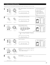
... 3 CH SEL ENTER CH SEL ENTER (Remote control unit) (Main unit) 4 CH SEL ENTER CH SEL ENTER (Remote control unit) (Main unit) Select the speaker to +6dB in 0.5dB step. (Remote control unit) 6 CH SEL ENTER (Main unit) CH SEL ENTER Enter the setting. 1-2 Setting the Manual EQ Setup ...Adjust the tone of the various speakers except subwoofer speaker while listening to the sound (music). 1 CH SEL ENTER CH SEL ENTER (Remote control unit) (Main unit) Select "Manual EQ Setup" at...
... 3 CH SEL ENTER CH SEL ENTER (Remote control unit) (Main unit) 4 CH SEL ENTER CH SEL ENTER (Remote control unit) (Main unit) Select the speaker to +6dB in 0.5dB step. (Remote control unit) 6 CH SEL ENTER (Main unit) CH SEL ENTER Enter the setting. 1-2 Setting the Manual EQ Setup ...Adjust the tone of the various speakers except subwoofer speaker while listening to the sound (music). 1 CH SEL ENTER CH SEL ENTER (Remote control unit) (Main unit) Select "Manual EQ Setup" at...


