Setup and Features Information Tech Sheet
Page 2
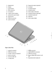
.... device status lights Figure 2. network connector 2. USB 2.0 connector 3. power connector 5. eSATA/USB 3.0 connector 9. Secure Digital (SD) memory-card slot 11. display latch 6. USB 2.0 connector 14. fingerprint reader (optional) 16. device status indicators 20. security cable slot 6. optical drive 13. wireless switch 19. trackstick (optional) 22. modem connector (optional) 4. VGA connector 9. Back View...
.... device status lights Figure 2. network connector 2. USB 2.0 connector 3. power connector 5. eSATA/USB 3.0 connector 9. Secure Digital (SD) memory-card slot 11. display latch 6. USB 2.0 connector 14. fingerprint reader (optional) 16. device status indicators 20. security cable slot 6. optical drive 13. wireless switch 19. trackstick (optional) 22. modem connector (optional) 4. VGA connector 9. Back View...
Setup and Features Information Tech Sheet
Page 3
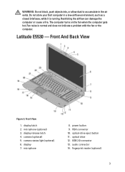
... 11. Fan noise is running. display latch 2. Restricting the airflow can damage the computer or cause a fire. Latitude E5530 - microphone 8. microphone (optional) 3. power button 9. Front View 1. The computer turns on the fan when the computer gets hot. camera (optional) 5. fingerprint reader (optional) 3 Do not store your Dell computer in the air vents. display release latch 4.
... 11. Fan noise is running. display latch 2. Restricting the airflow can damage the computer or cause a fire. Latitude E5530 - microphone 8. microphone (optional) 3. power button 9. Front View 1. The computer turns on the fan when the computer gets hot. camera (optional) 5. fingerprint reader (optional) 3 Do not store your Dell computer in the air vents. display release latch 4.
User Manual
Page 30
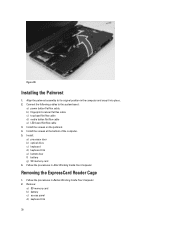
... : a) processor door b) optical drive c) keyboard d) keyboard trim e) bottom door f) battery g) SD memory card 6. Follow the procedures in After Working Inside Your Computer. Installing the Palmrest 1. b) fingerprint scanner flat flex cable c) touchpad flat flex cable d) media button flat flex cable e) LED board flat flex cable 3. Figure 30. Connect the following cables to... Install the screws at the bottom of the computer. 5. Align the palmrest assembly to the system board: a) power button flat flex cable. Removing the ExpressCard Reader Cage 1.
... : a) processor door b) optical drive c) keyboard d) keyboard trim e) bottom door f) battery g) SD memory card 6. Follow the procedures in After Working Inside Your Computer. Installing the Palmrest 1. b) fingerprint scanner flat flex cable c) touchpad flat flex cable d) media button flat flex cable e) LED board flat flex cable 3. Figure 30. Connect the following cables to... Install the screws at the bottom of the computer. 5. Align the palmrest assembly to the system board: a) power button flat flex cable. Removing the ExpressCard Reader Cage 1.


