Statement of Volatility
Page 2
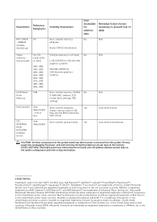
...Diskette Drives User replaceable Volatile memory in the U.S. Non-volatile magnetic Yes media, various sizes in this text: Dell™, the DELL logo, Dell Precision™, OptiPlex™, Latitude™, PowerEdge™, PowerVault™, PowerConnect™, OpenManage™, EqualLogic™, KACE™, FlexAddress™ ...of Red Hat, Inc. Primary power loss (unplugging the power cord and removing the battery) destroys all user data on the system board lose data if power is a registered trademark of Dell Inc. Microsoft®, Windows®, Windows Server®, MS-DOS®...
...Diskette Drives User replaceable Volatile memory in the U.S. Non-volatile magnetic Yes media, various sizes in this text: Dell™, the DELL logo, Dell Precision™, OptiPlex™, Latitude™, PowerEdge™, PowerVault™, PowerConnect™, OpenManage™, EqualLogic™, KACE™, FlexAddress™ ...of Red Hat, Inc. Primary power loss (unplugging the power cord and removing the battery) destroys all user data on the system board lose data if power is a registered trademark of Dell Inc. Microsoft®, Windows®, Windows Server®, MS-DOS®...
User Manual
Page 2
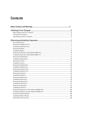
..., and Warnings 0 1 Working on Your Computer...5 Before Working Inside Your Computer...5 Turning Off Your Computer...6 After Working Inside Your Computer...6 2 Removing and Installing Components 7 Recommended Tools...7 Removing the SD Memory Card...7 Installing the SD Memory Card...7 Removing the Battery...7 Installing the Battery...8 Removing the Subscriber Identity Module (SIM) Card 8 Installing the Subscriber Identity Module (SIM) Card...
..., and Warnings 0 1 Working on Your Computer...5 Before Working Inside Your Computer...5 Turning Off Your Computer...6 After Working Inside Your Computer...6 2 Removing and Installing Components 7 Recommended Tools...7 Removing the SD Memory Card...7 Installing the SD Memory Card...7 Removing the Battery...7 Installing the Battery...8 Removing the Subscriber Identity Module (SIM) Card 8 Installing the Subscriber Identity Module (SIM) Card...
User Manual
Page 3
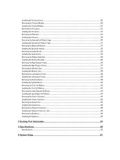
......39 Installing the System Board...42 Removing the Coin-Cell Battery...43 Installing the Coin-Cell Battery...43 Removing the Input/Output (I/O) Board...44 Installing the Input/Output (I/O) Board...44 Removing the Power Connector...45 Installing the Power Connector...46 Removing the System Fan...46 Installing the System Fan...48 Removing the Network Connector...48 Installing the...
......39 Installing the System Board...42 Removing the Coin-Cell Battery...43 Installing the Coin-Cell Battery...43 Removing the Input/Output (I/O) Board...44 Installing the Input/Output (I/O) Board...44 Removing the Power Connector...45 Installing the Power Connector...46 Removing the System Fan...46 Installing the System Fan...48 Removing the Network Connector...48 Installing the...

User Manual
Page 7
Removing the Battery 1. Removing and Installing Components This section provides detailed information on the SD memory card to remove or install the components from the computer. 3. Recommended Tools The procedures in After Working Inside Your Computer. Push the memory ... the procedures in this document may require the following tools: • Small flat-blade screwdriver • Phillips screwdriver • Small plastic scribe Removing the SD Memory Card 1. Follow the procedures in Before Working Inside Your Computer. 2. Slide the SD memory card out of the computer. Follow...
Removing the Battery 1. Removing and Installing Components This section provides detailed information on the SD memory card to remove or install the components from the computer. 3. Recommended Tools The procedures in After Working Inside Your Computer. Push the memory ... the procedures in this document may require the following tools: • Small flat-blade screwdriver • Phillips screwdriver • Small plastic scribe Removing the SD Memory Card 1. Follow the procedures in Before Working Inside Your Computer. 2. Slide the SD memory card out of the computer. Follow...

User Manual
Page 8
Figure 1. 3. Follow the procedures in After Working Inside Your Computer. Remove the battery. 3. Removing the Subscriber Identity Module (SIM) Card 1. Figure 2. Installing the Battery 1. Follow the procedures in Before Working Inside Your Computer. 2. Press and release the SIM card located on the battery wall. 8 Slide the battery into its slot until it clicks into place. 2. Remove the battery from the computer.
Figure 1. 3. Follow the procedures in After Working Inside Your Computer. Remove the battery. 3. Removing the Subscriber Identity Module (SIM) Card 1. Figure 2. Installing the Battery 1. Follow the procedures in Before Working Inside Your Computer. 2. Press and release the SIM card located on the battery wall. 8 Slide the battery into its slot until it clicks into place. 2. Remove the battery from the computer.

User Manual
Page 9
Slide the SIM card from the computer . 9 Installing the Subscriber Identity Module (SIM) Card 1. Pry up the bottom edge of the display bezel. . Figure 3. 5. Remove the display bezel from the computer. 4. Install the battery. 3. Remove the battery. 3. Follow the procedures in Before Working Inside Your Computer. 2. Insert the subscriber identity module (SIM) card into the slot. 2. Work your way around the sides and top edge of the display bezel. 4. Follow the procedures in After Working Inside Your Computer. Removing the Display Bezel 1.
Slide the SIM card from the computer . 9 Installing the Subscriber Identity Module (SIM) Card 1. Pry up the bottom edge of the display bezel. . Figure 3. 5. Remove the display bezel from the computer. 4. Install the battery. 3. Remove the battery. 3. Follow the procedures in Before Working Inside Your Computer. 2. Insert the subscriber identity module (SIM) card into the slot. 2. Work your way around the sides and top edge of the display bezel. 4. Follow the procedures in After Working Inside Your Computer. Removing the Display Bezel 1.

User Manual
Page 10
... 1. Tighten the screw that secure the display panel. 10 Place the display bezel onto the display assembly. 2. Install the battery. 4. Removing the Camera 1. Lift and remove the camera and microphone module. Install: a) display bezel b) battery 5. Remove the screw that secures the camera and microphone module. 5. Place the camera and microphone module in position on the...
... 1. Tighten the screw that secure the display panel. 10 Place the display bezel onto the display assembly. 2. Install the battery. 4. Removing the Camera 1. Lift and remove the camera and microphone module. Install: a) display bezel b) battery 5. Remove the screw that secures the camera and microphone module. 5. Place the camera and microphone module in position on the...

User Manual
Page 12
Align the display panel in its original position in the computer. 4. Install the display bezel. 7. Figure 7. Connect the low-voltage differential signaling (LVDS) cable to the display assembly. 3. Install the battery. 12 Attach the display panel to the display panel and attach the tape. 5. Remove the display panel from the display assembly. Install the screws that secure the display panel. 6. Flip the display panel over and install the screws that secure the display brackets to the display panel. 2. Installing the Display Panel 1. Figure 6. 6.
Align the display panel in its original position in the computer. 4. Install the display bezel. 7. Figure 7. Connect the low-voltage differential signaling (LVDS) cable to the display assembly. 3. Install the battery. 12 Attach the display panel to the display panel and attach the tape. 5. Remove the display panel from the display assembly. Install the screws that secure the display panel. 6. Flip the display panel over and install the screws that secure the display brackets to the display panel. 2. Installing the Display Panel 1. Figure 6. 6.

User Manual
Page 13
Pry up the keyboard trim starting from the computer. 13 Remove the battery. 3. Remove the screws at the back of the keyboard trim. 6. Follow the procedures in After Working Inside Your Computer. 8. Follow the procedures in Before Working Inside Your Computer. 2. Lift upwards and remove the keyboard trim from the bottom edge. 5. Removing the Keyboard Trim 1. Work your way around the sides and the top edge of the computer. 4.
Pry up the keyboard trim starting from the computer. 13 Remove the battery. 3. Remove the screws at the back of the keyboard trim. 6. Follow the procedures in After Working Inside Your Computer. 8. Follow the procedures in Before Working Inside Your Computer. 2. Lift upwards and remove the keyboard trim from the bottom edge. 5. Removing the Keyboard Trim 1. Work your way around the sides and the top edge of the computer. 4.

User Manual
Page 14
Follow the procedures in Before Working Inside Your Computer. 2. Removing the Keyboard 1. Remove: a) battery b) keyboard trim 3. Follow the procedures in After Working Inside Your Computer. Remove the screw at the back of the keyboard trim until it snaps in place. 3. Installing the Keyboard Trim 1. Press along the sides of the computer. 14 Install the battery. 4. Align the keyboard trim to its compartment. 2.
Follow the procedures in Before Working Inside Your Computer. 2. Removing the Keyboard 1. Remove: a) battery b) keyboard trim 3. Follow the procedures in After Working Inside Your Computer. Remove the screw at the back of the keyboard trim until it snaps in place. 3. Installing the Keyboard Trim 1. Press along the sides of the computer. 14 Install the battery. 4. Align the keyboard trim to its compartment. 2.

User Manual
Page 18
... secure the keyboard to the left and right side ensuring that secure the bottom door. Slide and then lift the bottom door upwards and remove it from the computer. 18 Install : a) keyboard trim b) battery 9. Install the screw at the back of the computer. 8. Follow the procedures in Before Working Inside Your Computer...
... secure the keyboard to the left and right side ensuring that secure the bottom door. Slide and then lift the bottom door upwards and remove it from the computer. 18 Install : a) keyboard trim b) battery 9. Install the screw at the back of the computer. 8. Follow the procedures in Before Working Inside Your Computer...

User Manual
Page 19
Install the screws that secures the optical drive. 19 Follow the procedures in After Working Inside Your Computer. Follow the procedures in Before Working Inside Your Computer. 2. Installing the Bottom Door 1. Removing the Optical Drive 1. Install the battery. 4. Figure 15. Remove the screw that secure the bottom door to the computer. 3. Remove: a) battery b) bottom door 3. Slide the bottom door into its slot until it clicks into place. 2.
Install the screws that secures the optical drive. 19 Follow the procedures in After Working Inside Your Computer. Follow the procedures in Before Working Inside Your Computer. 2. Installing the Bottom Door 1. Removing the Optical Drive 1. Install the battery. 4. Figure 15. Remove the screw that secure the bottom door to the computer. 3. Remove: a) battery b) bottom door 3. Slide the bottom door into its slot until it clicks into place. 2.

User Manual
Page 21
...Remove: 21 Remove the optical drive bezel. Install : a) bottom door b) battery 7. Follow the procedures in Before Working Inside Your Computer. 2. Install the screws that secures the optical drive in place. 6. Install the screw that secure the optical drive bracket. 4. Insert the optical drive into the computer. 5. Remove the optical drive bracket. 8. Removing... The Hard Drive 1. Follow the procedures in After Working Inside Your Computer. Remove the screws that secure the optical drive ...
...Remove: 21 Remove the optical drive bezel. Install : a) bottom door b) battery 7. Follow the procedures in Before Working Inside Your Computer. 2. Install the screws that secures the optical drive in place. 6. Install the screw that secure the optical drive bracket. 4. Insert the optical drive into the computer. 5. Remove the optical drive bracket. 8. Removing... The Hard Drive 1. Follow the procedures in After Working Inside Your Computer. Remove the screws that secure the optical drive ...

User Manual
Page 22
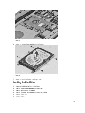
Use the tab to pull the hard drive bracket and release the hard drive from the computer. 22 Figure 20. 5. a) battery b) bottom door 3. Remove the screws that secure the hard drive bracket in place. Figure 19. 4. Remove the hard drive from its connector.
Use the tab to pull the hard drive bracket and release the hard drive from the computer. 22 Figure 20. 5. a) battery b) bottom door 3. Remove the screws that secure the hard drive bracket in place. Figure 19. 4. Remove the hard drive from its connector.
User Manual
Page 23
Figure 22. 7. Installing the Hard Drive 1. Install the hard drive into the computer. 4. Engage the hard drive bracket to the hard drive. 2. Install the screw that secure the hard drive bracket. 3. Install the screws that secures the hard drive bracket in place. 5. Remove the screws that secure the hard drive bracket. Remove the hard drive bracket from the hard drive. Install the bottom door. 6. Install the battery. 23 Figure 21. 6.
Figure 22. 7. Installing the Hard Drive 1. Install the hard drive into the computer. 4. Engage the hard drive bracket to the hard drive. 2. Install the screw that secure the hard drive bracket. 3. Install the screws that secures the hard drive bracket in place. 5. Remove the screws that secure the hard drive bracket. Remove the hard drive bracket from the hard drive. Install the bottom door. 6. Install the battery. 23 Figure 21. 6.
User Manual
Page 24
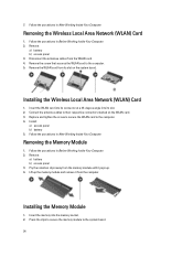
...card to the system board. 24 Install: a) access panel b) battery 5. Follow the procedures in Before Working Inside Your Computer. 2. Removing the Memory Module 1. Pry the retention clips away from its slot. 2. Removing the Wireless Local Area Network (WLAN) Card 1. Follow the ...to the computer. 4. Installing the Wireless Local Area Network (WLAN) Card 1. Remove: a) battery b) access panel 3. Installing the Memory Module 1. Follow the procedures in Before Working Inside Your Computer. 2. Remove the WLAN card from the memory module until it pops up the memory module ...
...card to the system board. 24 Install: a) access panel b) battery 5. Follow the procedures in Before Working Inside Your Computer. 2. Removing the Memory Module 1. Pry the retention clips away from its slot. 2. Removing the Wireless Local Area Network (WLAN) Card 1. Follow the ...to the computer. 4. Installing the Wireless Local Area Network (WLAN) Card 1. Remove: a) battery b) access panel 3. Installing the Memory Module 1. Follow the procedures in Before Working Inside Your Computer. 2. Remove the WLAN card from the memory module until it pops up the memory module ...
User Manual
Page 25
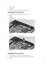
... door from the computer. Install : 25 Install: a) access panel b) battery 4. Install the screws that secure the processor door in its location at the bottom of the computer. 3. Removing the Processor Door 1. Installing the Processor Door 1. Place the processor door in place. Remove: a) battery b) bottom door 3. Remove the screws that secure the processor door to the...
... door from the computer. Install : 25 Install: a) access panel b) battery 4. Install the screws that secure the processor door in its location at the bottom of the computer. 3. Removing the Processor Door 1. Installing the Processor Door 1. Place the processor door in place. Remove: a) battery b) bottom door 3. Remove the screws that secure the processor door to the...

User Manual
Page 26
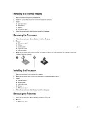
Follow the procedures in place. Remove the screws that secure the thermal module in Before Working Inside Your Computer. 2. Figure 25. 4. Figure 26. 26 Lift up the thermal module and remove it from the computer. Remove: a) SD memory card b) battery c) bottom door d) processor door 3. Follow the procedures in After Working Inside Your Computer. Removing the Thermal Module 1. a) bottom door b) battery 4.
Follow the procedures in place. Remove the screws that secure the thermal module in Before Working Inside Your Computer. 2. Figure 25. 4. Figure 26. 26 Lift up the thermal module and remove it from the computer. Remove: a) SD memory card b) battery c) bottom door d) processor door 3. Follow the procedures in After Working Inside Your Computer. Removing the Thermal Module 1. a) bottom door b) battery 4.
User Manual
Page 27
... processor cam lock in Before Working Inside Your Computer. 2. Install: a) thermal module b) access panel c) right base panel d) battery e) SD memory card 4. Install : a) processor door b) bottom door c) battery d) SD memory card 4. Lift up the processor and remove it from the computer. Follow the procedures in a clockwise direction to secure the processor. 3. Installing the Processor...
... processor cam lock in Before Working Inside Your Computer. 2. Install: a) thermal module b) access panel c) right base panel d) battery e) SD memory card 4. Install : a) processor door b) bottom door c) battery d) SD memory card 4. Lift up the processor and remove it from the computer. Follow the procedures in a clockwise direction to secure the processor. 3. Installing the Processor...
User Manual
Page 28
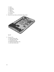
Remove the screws that secure the bottom of the computer. Disconnect the : a) LED board flat flex cable b) media button flat flex cable c) touchpad flat flex cable d) fingerprint scanner flat flex cable e) power button flat flex cable 28 Figure 27. 4. b) battery c) bottom door d) keyboard trim e) keyboard f) optical drive g) processor door h) hard drive 3.
Remove the screws that secure the bottom of the computer. Disconnect the : a) LED board flat flex cable b) media button flat flex cable c) touchpad flat flex cable d) fingerprint scanner flat flex cable e) power button flat flex cable 28 Figure 27. 4. b) battery c) bottom door d) keyboard trim e) keyboard f) optical drive g) processor door h) hard drive 3.


