Setup and Features Information Tech Sheet
Page 2
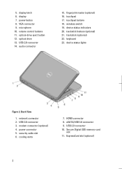
... (optional) 22. device status lights Figure 2. modem connector (optional) 4. USB 3.0 connector 10. display latch 6. device status indicators 20. cooling vents 7. display 7. touchpad buttons 18. eSATA/USB 3.0 connector 9. touchpad 17. optical drive 13. optical-drive eject button 12. fingerprint reader (optional) 16. keyboard 23. Back View 1. Secure Digital (SD) memory-card slot 11. power button 8. security cable slot 6. microphone 10. USB 2.0 connector 14. network connector 2. volume control buttons 11. 5. trackstick buttons (optional) 21. power...
... (optional) 22. device status lights Figure 2. modem connector (optional) 4. USB 3.0 connector 10. display latch 6. device status indicators 20. cooling vents 7. display 7. touchpad buttons 18. eSATA/USB 3.0 connector 9. touchpad 17. optical drive 13. optical-drive eject button 12. fingerprint reader (optional) 16. keyboard 23. Back View 1. Secure Digital (SD) memory-card slot 11. power button 8. security cable slot 6. microphone 10. USB 2.0 connector 14. network connector 2. volume control buttons 11. 5. trackstick buttons (optional) 21. power...
Setup and Features Information Tech Sheet
Page 3
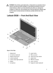
camera (optional) 5. camera status light (optional) 6. display 7. power button 9. optical drive 12. display latch 2. microphone 8. Do not store your Dell computer in the air vents. Latitude E5530 - Front And Back View Figure 3. audio connector 14. WARNING: Do not block, push objects into, or allow dust to accumulate in a low-airflow environment, such as a closed briefcase, while it is normal and does not indicate a problem with the fan or the...
camera (optional) 5. camera status light (optional) 6. display 7. power button 9. optical drive 12. display latch 2. microphone 8. Do not store your Dell computer in the air vents. Latitude E5530 - Front And Back View Figure 3. audio connector 14. WARNING: Do not block, push objects into, or allow dust to accumulate in a low-airflow environment, such as a closed briefcase, while it is normal and does not indicate a problem with the fan or the...
Setup and Features Information Tech Sheet
Page 4
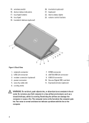
... your Dell computer in the air vents. 15. keyboard 22. device status lights 23. cooling vents 7. eSATA/USB 3.0 connector 9. The computer turns on the fan when the computer gets hot. Fan noise is running. USB 2.0 connector 3. HDMI connector 8. Restricting the airflow can damage the computer or cause a fire. touchpad 19. volume control buttons Figure 4. network connector 2. modem connector (optional) 4. Secure Digital (SD) card slot 11. trackstick (optional) 21. USB 3.0 connector 10. wireless switch...
... your Dell computer in the air vents. 15. keyboard 22. device status lights 23. cooling vents 7. eSATA/USB 3.0 connector 9. The computer turns on the fan when the computer gets hot. Fan noise is running. USB 2.0 connector 3. HDMI connector 8. Restricting the airflow can damage the computer or cause a fire. touchpad 19. volume control buttons Figure 4. network connector 2. modem connector (optional) 4. Secure Digital (SD) card slot 11. trackstick (optional) 21. USB 3.0 connector 10. wireless switch...
Statement of Volatility
Page 1
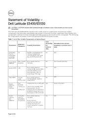
... Description Designator User Accessible for keyboard controller BIOS code, asset tag, and BIOS passwords. N/A Part of panel assembly System BIOS U18 Non-volatile memory, No 32 Mbit (4 MB), System BIOS and Video BIOS for correct operation of data and tells you how to four modules must be populated. On System Non-volatile memory No memory 512 Bytes. Dell Latitude E5430/E5530 CAUTION: A CAUTION indicates either potential damage to hardware or loss of system memory. List of...
... Description Designator User Accessible for keyboard controller BIOS code, asset tag, and BIOS passwords. N/A Part of panel assembly System BIOS U18 Non-volatile memory, No 32 Mbit (4 MB), System BIOS and Video BIOS for correct operation of data and tells you how to four modules must be populated. On System Non-volatile memory No memory 512 Bytes. Dell Latitude E5430/E5530 CAUTION: A CAUTION indicates either potential damage to hardware or loss of system memory. List of...
Statement of Volatility
Page 2
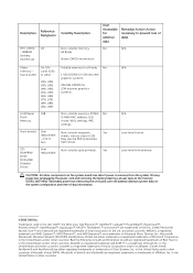
... buffer On GFx cards (G92 or G94): U2A, U2B, U3A, U3B, U4A, U4B, U5A, U5B, U6A, U6B, U7A, U7B, U8A, U8B, U9A, U9B LOM Serial U18 Flash Memory Hard drive(s) User replaceable - one or two. Non-volatile magnetic Yes media, various sizes in the United States and/or other countries. Secondary power loss (removing the on-board coin-cell battery) destroys system data...
... buffer On GFx cards (G92 or G94): U2A, U2B, U3A, U3B, U4A, U4B, U5A, U5B, U6A, U6B, U7A, U7B, U8A, U8B, U9A, U9B LOM Serial U18 Flash Memory Hard drive(s) User replaceable - one or two. Non-volatile magnetic Yes media, various sizes in the United States and/or other countries. Secondary power loss (removing the on-board coin-cell battery) destroys system data...
User Manual
Page 2
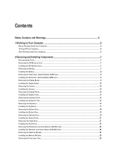
...the Camera...10 Installing the Camera...10 Removing the Display Panel...10 Installing the Display Panel...12 Removing the Keyboard Trim...13 Installing the Keyboard Trim...14 Removing the Keyboard...14 Installing the Keyboard...17 Removing the Bottom Door...18 Installing the Bottom Door...19 Removing the Optical Drive...19 Installing the Optical Drive...21 Removing The Hard Drive...21 Installing the Hard Drive...23 Removing the Wireless Local Area Network (WLAN) Card 24 Installing the Wireless Local Area Network (WLAN) Card 24 Removing the Memory Module...24 Installing the Memory Module...24...
...the Camera...10 Installing the Camera...10 Removing the Display Panel...10 Installing the Display Panel...12 Removing the Keyboard Trim...13 Installing the Keyboard Trim...14 Removing the Keyboard...14 Installing the Keyboard...17 Removing the Bottom Door...18 Installing the Bottom Door...19 Removing the Optical Drive...19 Installing the Optical Drive...21 Removing The Hard Drive...21 Installing the Hard Drive...23 Removing the Wireless Local Area Network (WLAN) Card 24 Installing the Wireless Local Area Network (WLAN) Card 24 Removing the Memory Module...24 Installing the Memory Module...24...

User Manual
Page 3
... Board...39 Installing the System Board...42 Removing the Coin-Cell Battery...43 Installing the Coin-Cell Battery...43 Removing the Input/Output (I/O) Board...44 Installing the Input/Output (I/O) Board...44 Removing the Power Connector...45 Installing the Power Connector...46 Removing the System Fan...46 Installing the System Fan...48 Removing the Network Connector...48 Installing the Network Connector Jack...49 Removing the Speakers...49 Installing the Speakers...50 3 Docking Port Information...53 4 Specifications...55 Specifications...55 5 System Setup...
... Board...39 Installing the System Board...42 Removing the Coin-Cell Battery...43 Installing the Coin-Cell Battery...43 Removing the Input/Output (I/O) Board...44 Installing the Input/Output (I/O) Board...44 Removing the Power Connector...45 Installing the Power Connector...46 Removing the System Fan...46 Installing the System Fan...48 Removing the Network Connector...48 Installing the Network Connector Jack...49 Removing the Speakers...49 Installing the Speakers...50 3 Docking Port Information...53 4 Specifications...55 Specifications...55 5 System Setup...
User Manual
Page 5
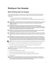
... not authorized by Dell is not covered by its metal mounting bracket. While you begin working inside your computer, ground yourself by the online or telephone service and support team. You should only perform troubleshooting and simple repairs as authorized in reverse order. NOTE: The color of the computer. Working on Your Computer Before Working Inside Your Computer Use the following...
... not authorized by Dell is not covered by its metal mounting bracket. While you begin working inside your computer, ground yourself by the online or telephone service and support team. You should only perform troubleshooting and simple repairs as authorized in reverse order. NOTE: The color of the computer. Working on Your Computer Before Working Inside Your Computer Use the following...
User Manual
Page 6
... Windows Vista: Click Start , then click the arrow in the lower-right corner of the Start menu as shown below, and then click Shut Down. - If your computer and attached devices did not automatically turn off when you connect any replacement procedure, ensure you shut down the operating system: - After Working Inside Your Computer After you complete any external devices, cards, and cables before you turn...
... Windows Vista: Click Start , then click the arrow in the lower-right corner of the Start menu as shown below, and then click Shut Down. - If your computer and attached devices did not automatically turn off when you connect any replacement procedure, ensure you shut down the operating system: - After Working Inside Your Computer After you complete any external devices, cards, and cables before you turn...
User Manual
Page 24
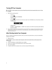
.... Remove the WLAN card from its slot. 2. Replace and tighten the screw to secure the WLAN card to the computer. 5. Install: a) access panel b) battery 5. Removing the Wireless Local Area Network (WLAN) Card 1. Remove the screw that secures the WLAN card to the computer. 4. Remove: a) battery b) access panel 3. Installing the Wireless Local Area Network (WLAN) Card 1. Connect the antenna cables to the system board. 24 Removing the Memory Module 1. Follow the procedures in After Working Inside Your Computer. Lift up the memory module...
.... Remove the WLAN card from its slot. 2. Replace and tighten the screw to secure the WLAN card to the computer. 5. Install: a) access panel b) battery 5. Removing the Wireless Local Area Network (WLAN) Card 1. Remove the screw that secures the WLAN card to the computer. 4. Remove: a) battery b) access panel 3. Installing the Wireless Local Area Network (WLAN) Card 1. Connect the antenna cables to the system board. 24 Removing the Memory Module 1. Follow the procedures in After Working Inside Your Computer. Lift up the memory module...
User Manual
Page 31
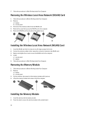
... computer. Install: a) palmrest b) right base panel c) optical drive d) keyboard e) keyboard trim f) access panel g) battery h) SD memory card 4. Remove: a) SD memory card b) battery c) bottom door d) keyboard trim e) keyboard f) optical drive g) processor door h) palm rest 3. e) keyboard f) optical drive g) right base panel h) palmrest 3. Align the ExpressCard reader cage to its original position in Before Working Inside Your Computer. 2. Follow the procedures in the computer and snap it into place. 2. Remove the screws that secures the Bluetooth module in...
... computer. Install: a) palmrest b) right base panel c) optical drive d) keyboard e) keyboard trim f) access panel g) battery h) SD memory card 4. Remove: a) SD memory card b) battery c) bottom door d) keyboard trim e) keyboard f) optical drive g) processor door h) palm rest 3. e) keyboard f) optical drive g) right base panel h) palmrest 3. Align the ExpressCard reader cage to its original position in Before Working Inside Your Computer. 2. Follow the procedures in the computer and snap it into place. 2. Remove the screws that secures the Bluetooth module in...
User Manual
Page 32
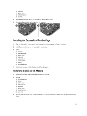
Installing the Bluetooth module 1. Connect the Bluetooth cable to the system board. 5. Install : a) palm rest b) processor door c) optical drive d) keyboard e) keyboard trim f) bottom door g) battery h) SD memory card 6. Follow the procedures in After Working Inside Your Computer. Remove the optical drive. 8. Remove the Bluetooth module. 11. Place the Bluetooth module into its compartment on the computer. 3. Remove the battery. 4. Remove the keyboard trim. 6. Disconnect the Bluetooth cable from the computer. 5. Follow the procedures in Before Working Inside Your...
Installing the Bluetooth module 1. Connect the Bluetooth cable to the system board. 5. Install : a) palm rest b) processor door c) optical drive d) keyboard e) keyboard trim f) bottom door g) battery h) SD memory card 6. Follow the procedures in After Working Inside Your Computer. Remove the optical drive. 8. Remove the Bluetooth module. 11. Place the Bluetooth module into its compartment on the computer. 3. Remove the battery. 4. Remove the keyboard trim. 6. Disconnect the Bluetooth cable from the computer. 5. Follow the procedures in Before Working Inside Your...
User Manual
Page 56
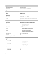
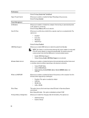
Audio Internal speaker amplifier Volume controls Video Type Controller Communications Network adapter Wireless Ports and Connectors Audio (optional) Video Network adapter USB 2.0 USB 3.0 Memory card reader Docking port Subscriber Identity Module (SIM) port Display Type Latitude E5430 Latitude E5530 Size Latitude E5430 Latitude E5530 Dimensions: 56 1W (RMS) per channel keyboard function keys, program menus integrated on system board Intel HD Graphics 10/100/1000 Mb/s Ethernet (RJ-45) internal wireless local area network (WLAN) and wireless wide area network (WWAN) one microphone/stereo ...
Audio Internal speaker amplifier Volume controls Video Type Controller Communications Network adapter Wireless Ports and Connectors Audio (optional) Video Network adapter USB 2.0 USB 3.0 Memory card reader Docking port Subscriber Identity Module (SIM) port Display Type Latitude E5430 Latitude E5530 Size Latitude E5430 Latitude E5530 Dimensions: 56 1W (RMS) per channel keyboard function keys, program menus integrated on system board Intel HD Graphics 10/100/1000 Mb/s Ethernet (RJ-45) internal wireless local area network (WLAN) and wireless wide area network (WWAN) one microphone/stereo ...
User Manual
Page 61
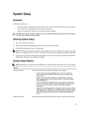
...; set or change a user-selectable option such as the user password. • read the current amount of memory or set the type of hard drive installed. Entering System Setup 1. NOTE: The F2 prompt indicates that the keyboard has initialized. Then, shut down your computer. • System Information: Displays BIOS Version, Service Tag, Asset Tag, Ownership Tag, Ownership Date, Manufacture Date, and the Express Service Code. • Memory Information: Displays Memory Installed, Memory Available, Memory Speed, Memory Channels Mode, Memory Technology...
...; set or change a user-selectable option such as the user password. • read the current amount of memory or set the type of hard drive installed. Entering System Setup 1. NOTE: The F2 prompt indicates that the keyboard has initialized. Then, shut down your computer. • System Information: Displays BIOS Version, Service Tag, Asset Tag, Ownership Tag, Ownership Date, Manufacture Date, and the Express Service Code. • Memory Information: Displays Memory Installed, Memory Available, Memory Speed, Memory Channels Mode, Memory Technology...
User Manual
Page 63
... port. • Enable Boot Support • Enable External USB Port NOTE: USB keyboard and mouse always work in the BIOS setup irrespective of the keyboard illumination feature. Allows you choose the operating mode of these settings. This technology is part of USB Mass Storage Devices (HDD, memory key, floppy). If USB port is disabled, the OS cannot see any type of the SMART (Self Monitoring Analysis and Reporting Technology) specification. The keyboard brightness level can be set from 25% to configure the SATA drives on board...
... port. • Enable Boot Support • Enable External USB Port NOTE: USB keyboard and mouse always work in the BIOS setup irrespective of the keyboard illumination feature. Allows you choose the operating mode of these settings. This technology is part of USB Mass Storage Devices (HDD, memory key, floppy). If USB port is disabled, the OS cannot see any type of the SMART (Self Monitoring Analysis and Reporting Technology) specification. The keyboard brightness level can be set from 25% to configure the SATA drives on board...
User Manual
Page 65
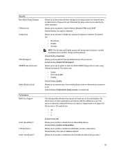
... cores enabled. If disabled the setup options are locked by default.Allows you to enable or disable multi-core support for the processor. Default Setting: The option C statesis enabled. Default Setting: Enable CPU XD Support Allows you to set an option to enter the Option ROM Configuration screens using hotkeys during POST. The performance of the processor. 65 Security Non-Admin Setup Changes TPM Security Computrace CPU XD Support OROM Keyboard Access Admin Setup Lockout Performance Multi Core Support Intel® SpeedStep™ C States Control Intel...
... cores enabled. If disabled the setup options are locked by default.Allows you to enable or disable multi-core support for the processor. Default Setting: The option C statesis enabled. Default Setting: Enable CPU XD Support Allows you to set an option to enter the Option ROM Configuration screens using hotkeys during POST. The performance of the processor. 65 Security Non-Admin Setup Changes TPM Security Computrace CPU XD Support OROM Keyboard Access Admin Setup Lockout Performance Multi Core Support Intel® SpeedStep™ C States Control Intel...
User Manual
Page 66
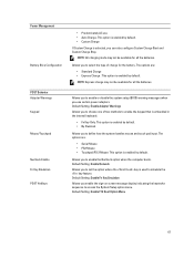
... entering to wake the system from turning on automatically when an AC adapter is not selected. This option is enabled by default. The options are : • Disabled • Every Day • Weekdays • Select Days Default Setting: Disabled Allows you to enable USB devices to sleep (S3 state) in the processor. Default Setting: Wake on AC is connected. Default Setting: Enabled Allows you to select the charging mode for the battery. Performance Hyper-Thread Control Power Management...
... entering to wake the system from turning on automatically when an AC adapter is not selected. This option is enabled by default. The options are : • Disabled • Every Day • Weekdays • Select Days Default Setting: Disabled Allows you to enable USB devices to sleep (S3 state) in the processor. Default Setting: Wake on AC is connected. Default Setting: Enabled Allows you to select the charging mode for the battery. Performance Hyper-Thread Control Power Management...
User Manual
Page 67
...Setting: Enable Network Allows you to set the option where the key is enabled by default. Default Setting: Enable F12 Boot Option Menu 67 Default Setting: Enable Fn Key Emulation Allows you to define how the system handles mouse and touch pad input. Power Management Battery Slice Configuration POST Behavior Adapter Warnings Keypad Mouse/Touchpad Numlock Enable Fn Key Emulation POST HotKeys • Predominately AC use certain power adapters. Allows you enable the sign-on screen message display indicating the keystroke sequence to simulate the key feature. NOTE: All charging...
...Setting: Enable Network Allows you to set the option where the key is enabled by default. Default Setting: Enable F12 Boot Option Menu 67 Default Setting: Enable Fn Key Emulation Allows you to define how the system handles mouse and touch pad input. Power Management Battery Slice Configuration POST Behavior Adapter Warnings Keypad Mouse/Touchpad Numlock Enable Fn Key Emulation POST HotKeys • Predominately AC use certain power adapters. Allows you enable the sign-on screen message display indicating the keystroke sequence to simulate the key feature. NOTE: All charging...
User Manual
Page 68
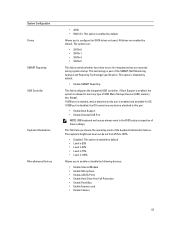
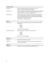
... be controlled by Intel® Virtualization technology for direct I /O Trusted Execution Wireless Wireless Switch Wireless Device Enable Maintenance Service Tag Asset Tag System Logs BIOS Events Allows you to create a system asset tag if an asset tag is enabled by default. The options are: • WWAN • WLAN • Bluetooth All the options are enabled by default. Allows you to view and clear the System Setup (BIOS) POST events. 68 Virtualization Support...
... be controlled by Intel® Virtualization technology for direct I /O Trusted Execution Wireless Wireless Switch Wireless Device Enable Maintenance Service Tag Asset Tag System Logs BIOS Events Allows you to create a system asset tag if an asset tag is enabled by default. The options are: • WWAN • WLAN • Bluetooth All the options are enabled by default. Allows you to view and clear the System Setup (BIOS) POST events. 68 Virtualization Support...
User Manual
Page 69
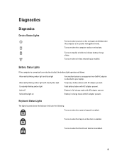
... Lock function is in a power management mode. Battery Status Lights If the computer is connected to an electrical outlet, the battery light operates as follows: Alternately blinking amber light and blue light Alternately blinking amber light with steady blue light Constantly blinking amber light Light off Solid white light on An unauthenticated or unsupported non-Dell AC adapter is enabled. 69 Battery in full charge mode with AC adapter present. Turns on steadily or blinks to your laptop. Diagnostics Diagnostics Device Status Lights Turns...
... Lock function is in a power management mode. Battery Status Lights If the computer is connected to an electrical outlet, the battery light operates as follows: Alternately blinking amber light and blue light Alternately blinking amber light with steady blue light Constantly blinking amber light Light off Solid white light on An unauthenticated or unsupported non-Dell AC adapter is enabled. 69 Battery in full charge mode with AC adapter present. Turns on steadily or blinks to your laptop. Diagnostics Diagnostics Device Status Lights Turns...


