Setup and Features Information Tech Sheet
Page 2
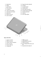
display latch 6. VGA connector 9. optical drive 13. security cable slot 6. Secure Digital (SD) memory-card slot 11. power button 8. touchpad 17. trackstick buttons (optional) 21. Back View 1. network connector 2. USB 2.0 connector 3. volume control buttons 11. audio connector 15. keyboard ...
display latch 6. VGA connector 9. optical drive 13. security cable slot 6. Secure Digital (SD) memory-card slot 11. power button 8. touchpad 17. trackstick buttons (optional) 21. Back View 1. network connector 2. USB 2.0 connector 3. volume control buttons 11. audio connector 15. keyboard ...
Statement of Volatility
Page 1
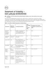
... will depend on System Board Reference Description Volatility Description Designator User Accessible for basic boot operation, PSA (on the Dell Latitude E5430/E5530 system board. DDR3 memory System memory SPD EEPROM On GFx Non-volatile memory, No cards 512 kbit (64 KB), Graphics (G92 or G94) system BIOS. N/A N/A Power off system N/A Page 1 of panel Non-volatile...
... will depend on System Board Reference Description Volatility Description Designator User Accessible for basic boot operation, PSA (on the Dell Latitude E5430/E5530 system board. DDR3 memory System memory SPD EEPROM On GFx Non-volatile memory, No cards 512 kbit (64 KB), Graphics (G92 or G94) system BIOS. N/A N/A Power off system N/A Page 1 of panel Non-volatile...
Statement of Volatility
Page 2
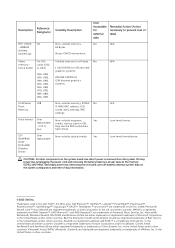
...174;, vCenter®, and vSphere® are registered trademarks of Intel Corporation in this text: Dell™, the DELL logo, Dell Precision™, OptiPlex™, Latitude™, PowerEdge™, PowerVault™, PowerConnect™, OpenManage™, EqualLogic™, KACE™, ...FlexAddress™ and Vostro™ are trademarks of VMWare, Inc. BBRAM (battery backed up) Non-volatile memory, 64...
...174;, vCenter®, and vSphere® are registered trademarks of Intel Corporation in this text: Dell™, the DELL logo, Dell Precision™, OptiPlex™, Latitude™, PowerEdge™, PowerVault™, PowerConnect™, OpenManage™, EqualLogic™, KACE™, ...FlexAddress™ and Vostro™ are trademarks of VMWare, Inc. BBRAM (battery backed up) Non-volatile memory, 64...
User Manual
Page 2
... Inside Your Computer...5 Turning Off Your Computer...6 After Working Inside Your Computer...6 2 Removing and Installing Components 7 Recommended Tools...7 Removing the SD Memory Card...7 Installing the SD Memory Card...7 Removing the Battery...7 Installing the Battery...8 Removing the Subscriber Identity Module (SIM) Card 8 Installing the Subscriber Identity Module (SIM) Card...Removing the Wireless Local Area Network (WLAN) Card 24 Installing the Wireless Local Area Network (WLAN) Card 24 Removing the Memory Module...24 Installing the Memory Module...24 Removing the Processor Door...25
... Inside Your Computer...5 Turning Off Your Computer...6 After Working Inside Your Computer...6 2 Removing and Installing Components 7 Recommended Tools...7 Removing the SD Memory Card...7 Installing the SD Memory Card...7 Removing the Battery...7 Installing the Battery...8 Removing the Subscriber Identity Module (SIM) Card 8 Installing the Subscriber Identity Module (SIM) Card...Removing the Wireless Local Area Network (WLAN) Card 24 Installing the Wireless Local Area Network (WLAN) Card 24 Removing the Memory Module...24 Installing the Memory Module...24 Removing the Processor Door...25

User Manual
Page 7
...may require the following tools: • Small flat-blade screwdriver • Phillips screwdriver • Small plastic scribe Removing the SD Memory Card 1. Slide the SD memory card out of the computer. Removing the Battery 1. Follow the procedures in Before Working Inside Your Computer. 2. Slide the battery...the procedures in Before Working Inside Your Computer. 2. Removing and Installing Components This section provides detailed information on the SD memory card to remove or install the components from the computer. 3. Press in on how to release it clicks into place. 2. Push ...
...may require the following tools: • Small flat-blade screwdriver • Phillips screwdriver • Small plastic scribe Removing the SD Memory Card 1. Slide the SD memory card out of the computer. Removing the Battery 1. Follow the procedures in Before Working Inside Your Computer. 2. Slide the battery...the procedures in Before Working Inside Your Computer. 2. Removing and Installing Components This section provides detailed information on the SD memory card to remove or install the components from the computer. 3. Press in on how to release it clicks into place. 2. Push ...
User Manual
Page 24
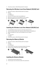
... Remove the WLAN card from its slot. 2. Connect the antenna cables to the computer. 4. Removing the Memory Module 1. Installing the Memory Module 1. Press the clips to secure the memory module to the computer. 5. Remove: a) battery b) access panel 3. Insert the WLAN card into its ...in Before Working Inside Your Computer. 2. Follow the procedures in After Working Inside Your Computer. Pry the retention clips away from the memory module until it from the WLAN card. 4. 7. Follow the procedures in After Working Inside Your Computer. Installing the Wireless Local Area...
... Remove the WLAN card from its slot. 2. Connect the antenna cables to the computer. 4. Removing the Memory Module 1. Installing the Memory Module 1. Press the clips to secure the memory module to the computer. 5. Remove: a) battery b) access panel 3. Insert the WLAN card into its ...in Before Working Inside Your Computer. 2. Follow the procedures in After Working Inside Your Computer. Pry the retention clips away from the memory module until it from the WLAN card. 4. 7. Follow the procedures in After Working Inside Your Computer. Installing the Wireless Local Area...

User Manual
Page 26
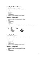
a) bottom door b) battery 4. Follow the procedures in After Working Inside Your Computer. Figure 25. 4. Follow the procedures in Before Working Inside Your Computer. 2. Remove the screws that secure the thermal module in place. Figure 26. 26 Remove: a) SD memory card b) battery c) bottom door d) processor door 3. Lift up the thermal module and remove it from the computer. Removing the Thermal Module 1.
a) bottom door b) battery 4. Follow the procedures in After Working Inside Your Computer. Figure 25. 4. Follow the procedures in Before Working Inside Your Computer. 2. Remove the screws that secure the thermal module in place. Figure 26. 26 Remove: a) SD memory card b) battery c) bottom door d) processor door 3. Lift up the thermal module and remove it from the computer. Removing the Thermal Module 1.
User Manual
Page 27
... the processor cam lock in its compartment. 2. Install: a) thermal module b) access panel c) right base panel d) battery e) SD memory card 4. Follow the procedures in After Working Inside Your Computer. Follow the procedures in Before Working Inside Your Computer. 2. Removing the ...the screws that secure the thermal module to the unlock position. Install : a) processor door b) bottom door c) battery d) SD memory card 4. Remove: a) SD memory card b) battery c) access panel d) right base panel e) thermal module 3. Follow the procedures in a counter clockwise direction to the computer...
... the processor cam lock in its compartment. 2. Install: a) thermal module b) access panel c) right base panel d) battery e) SD memory card 4. Follow the procedures in After Working Inside Your Computer. Follow the procedures in Before Working Inside Your Computer. 2. Removing the ...the screws that secure the thermal module to the unlock position. Install : a) processor door b) bottom door c) battery d) SD memory card 4. Remove: a) SD memory card b) battery c) access panel d) right base panel e) thermal module 3. Follow the procedures in a counter clockwise direction to the computer...
User Manual
Page 30
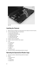
Connect the following cables to its original position in the computer and snap it into place. 2. Remove: a) SD memory card b) battery c) access panel d) keyboard trim 30 Installing the Palmrest 1. Align the palmrest assembly to the system board:... the procedures in After Working Inside Your Computer. Install : a) processor door b) optical drive c) keyboard d) keyboard trim e) bottom door f) battery g) SD memory card 6. Figure 30. Install the screws on the palmrest. 4. Follow the procedures in Before Working Inside Your Computer. 2. b) fingerprint scanner flat flex cable ...
Connect the following cables to its original position in the computer and snap it into place. 2. Remove: a) SD memory card b) battery c) access panel d) keyboard trim 30 Installing the Palmrest 1. Align the palmrest assembly to the system board:... the procedures in After Working Inside Your Computer. Install : a) processor door b) optical drive c) keyboard d) keyboard trim e) bottom door f) battery g) SD memory card 6. Figure 30. Install the screws on the palmrest. 4. Follow the procedures in Before Working Inside Your Computer. 2. b) fingerprint scanner flat flex cable ...
User Manual
Page 31
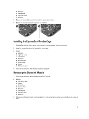
... Follow the procedures in the computer and snap it into place. 2. Disconnect the Bluetooth cable from the computer. Installing the ExpressCard Reader Cage 1. Remove: a) SD memory card b) battery c) bottom door d) keyboard trim e) keyboard f) optical drive g) processor door h) palm rest 3. e) keyboard f) optical drive g) right base panel... in place. 31 Install: a) palmrest b) right base panel c) optical drive d) keyboard e) keyboard trim f) access panel g) battery h) SD memory card 4. Removing the Bluetooth Module 1. Remove the screws that secure the ExpressCard reader cage. 3.
... Follow the procedures in the computer and snap it into place. 2. Disconnect the Bluetooth cable from the computer. Installing the ExpressCard Reader Cage 1. Remove: a) SD memory card b) battery c) bottom door d) keyboard trim e) keyboard f) optical drive g) processor door h) palm rest 3. e) keyboard f) optical drive g) right base panel... in place. 31 Install: a) palmrest b) right base panel c) optical drive d) keyboard e) keyboard trim f) access panel g) battery h) SD memory card 4. Removing the Bluetooth Module 1. Remove the screws that secure the ExpressCard reader cage. 3.
User Manual
Page 32
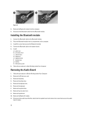
.... 5. Follow the procedures in Before Working Inside Your Computer. 2. Remove the battery. 4. Remove the keyboard trim. 6. Remove the palmrest. 10. Figure 31. 4. Remove the SD memory card. 3. Connect the Bluetooth cable to the Bluetooth module. 2. Place the Bluetooth module into its compartment on the computer. 3. Remove the Bluetooth module. 11. Install...
.... 5. Follow the procedures in Before Working Inside Your Computer. 2. Remove the battery. 4. Remove the keyboard trim. 6. Remove the palmrest. 10. Figure 31. 4. Remove the SD memory card. 3. Connect the Bluetooth cable to the Bluetooth module. 2. Place the Bluetooth module into its compartment on the computer. 3. Remove the Bluetooth module. 11. Install...
User Manual
Page 33
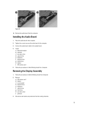
... board. 4. Follow the procedures in After Working Inside Your Computer. Install: a) Bluetooth module b) palmrest c) processor door d) optical drive e) keyboard f) keyboard trim g) bottom door h) battery i) SD memory card 5. Place the audio board in the computer. 2. Removing the Display Assembly 1. Disconnect and remove any antennas from the computer. Figure 32. 12. Connect the...
... board. 4. Follow the procedures in After Working Inside Your Computer. Install: a) Bluetooth module b) palmrest c) processor door d) optical drive e) keyboard f) keyboard trim g) bottom door h) battery i) SD memory card 5. Place the audio board in the computer. 2. Removing the Display Assembly 1. Disconnect and remove any antennas from the computer. Figure 32. 12. Connect the...
User Manual
Page 36
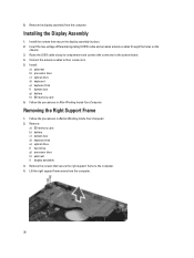
...their connectors. 5. Follow the procedures in After Working Inside Your Computer. Install the screws that secure the right support frame to the computer. 4. Remove: a) SD memory card b) battery c) bottom door d) keyboard trim e) optical drive f) hard drive g) processor door h) palmrest i) display assembly 3. Removing the Right Support Frame ... the chassis. 3. 8. Installing the Display Assembly 1. Install : a) palmrest b) processor door c) optical drive d) keyboard e) keyboard trim f) bottom door g) battery h) SD memory card 6. Remove the display assembly from the computer. 36
...their connectors. 5. Follow the procedures in After Working Inside Your Computer. Install the screws that secure the right support frame to the computer. 4. Remove: a) SD memory card b) battery c) bottom door d) keyboard trim e) optical drive f) hard drive g) processor door h) palmrest i) display assembly 3. Removing the Right Support Frame ... the chassis. 3. 8. Installing the Display Assembly 1. Install : a) palmrest b) processor door c) optical drive d) keyboard e) keyboard trim f) bottom door g) battery h) SD memory card 6. Remove the display assembly from the computer. 36
User Manual
Page 37
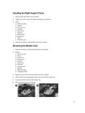
... from the connector on the computer. 2. Tighten the screws to secure the right support frame to the computer. 4. Installing the Right Support Frame 1. Remove: a) SD memory card b) battery c) bottom door d) keyboard trim e) keyboard f) optical drive g) hard drive h) processor door i) palmrest j) display assembly k) right support frame 3. Place the right support ... in After Working Inside Your Computer. Install: a) display assembly b) palmrest c) processor door d) hard drive e) optical drive f) keyboard g) keyboard trim h) bottom doorl i) battery j) SD memory card 4.
... from the connector on the computer. 2. Tighten the screws to secure the right support frame to the computer. 4. Installing the Right Support Frame 1. Remove: a) SD memory card b) battery c) bottom door d) keyboard trim e) keyboard f) optical drive g) hard drive h) processor door i) palmrest j) display assembly k) right support frame 3. Place the right support ... in After Working Inside Your Computer. Install: a) display assembly b) palmrest c) processor door d) hard drive e) optical drive f) keyboard g) keyboard trim h) bottom doorl i) battery j) SD memory card 4.
User Manual
Page 38
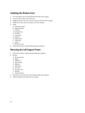
... b) display assembly c) palmrest d) processor door e) hard drive f) optical drive g) keyboard h) keyboard trim i) bottom door j) battery k) SD memory card 6. Remove the screws that secure the left support frame away from the computer. 38 Lift the left support frame to the computer. 5. ...Place the modem card on the Input/Output (I/O) board in Before Working Inside Your Computer. 2. Remove: a) SD memory card b) battery c) bottom door d) keyboard trim e) keyboard f) optical drive g) hard drive h) processor door i) palmrest j) display assembly 3. Installing...
... b) display assembly c) palmrest d) processor door e) hard drive f) optical drive g) keyboard h) keyboard trim i) bottom door j) battery k) SD memory card 6. Remove the screws that secure the left support frame away from the computer. 38 Lift the left support frame to the computer. 5. ...Place the modem card on the Input/Output (I/O) board in Before Working Inside Your Computer. 2. Remove: a) SD memory card b) battery c) bottom door d) keyboard trim e) keyboard f) optical drive g) hard drive h) processor door i) palmrest j) display assembly 3. Installing...
User Manual
Page 39
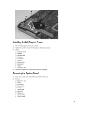
... screws to the computer. 3. Install: a) display assembly b) palmrest c) processor door d) hard drive e) optical drive f) keyboard g) keyboard trim h) bottom door i) battery j) SD memory card 4. Removing the System Board 1. Remove: a) SD memory card b) battery c) bottom door d) keyboard trim e) keyboard f) optical drive g) hard drive h) WLAN card i) processor door j) thermal module 39 Place the left support...
... screws to the computer. 3. Install: a) display assembly b) palmrest c) processor door d) hard drive e) optical drive f) keyboard g) keyboard trim h) bottom door i) battery j) SD memory card 4. Removing the System Board 1. Remove: a) SD memory card b) battery c) bottom door d) keyboard trim e) keyboard f) optical drive g) hard drive h) WLAN card i) processor door j) thermal module 39 Place the left support...
User Manual
Page 42
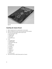
... : a) left support frame b) display assembly c) ExpressCard reader cage d) palm rest e) thermal module f) processor door g) hard drive h) optical drive i) keyboard j) keyboard trim k) bottom door l) battery m) SD memory card 5. Align the system board into its original position on the computer. 2.
... : a) left support frame b) display assembly c) ExpressCard reader cage d) palm rest e) thermal module f) processor door g) hard drive h) optical drive i) keyboard j) keyboard trim k) bottom door l) battery m) SD memory card 5. Align the system board into its original position on the computer. 2.
User Manual
Page 43
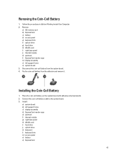
... board 3. Pry the coin-cell battery from the system board. 4. Place the coin-cell battery on the system board with adhesive side downwards. 2. Remove: a) SD memory card b) ExpressCard c) battery d) access panel e) keyboard trim f) optical drive g) hard drive h) WLAN card i) right base panel j) thermal module k) palmrest l) ExpressCard reader cage m) display assembly n) left...
... board 3. Pry the coin-cell battery from the system board. 4. Place the coin-cell battery on the system board with adhesive side downwards. 2. Remove: a) SD memory card b) ExpressCard c) battery d) access panel e) keyboard trim f) optical drive g) hard drive h) WLAN card i) right base panel j) thermal module k) palmrest l) ExpressCard reader cage m) display assembly n) left...
User Manual
Page 44
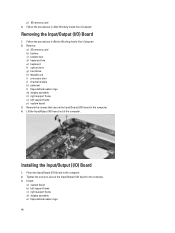
Remove: a) SD memory card b) battery c) bottom door d) keyboard trim e) keyboard f) optical drive g) hard drive h) WLAN card i) processor door j) thermal module k) palmrest l) ExpressCard reader cage m) display assembly n) right support ... Inside Your Computer. Follow the procedures in Before Working Inside Your Computer. 2. Tighten the screw to secure the Input/Output (I/O) board to the computer. 3. p) SD memory card 4.
Remove: a) SD memory card b) battery c) bottom door d) keyboard trim e) keyboard f) optical drive g) hard drive h) WLAN card i) processor door j) thermal module k) palmrest l) ExpressCard reader cage m) display assembly n) right support ... Inside Your Computer. Follow the procedures in Before Working Inside Your Computer. 2. Tighten the screw to secure the Input/Output (I/O) board to the computer. 3. p) SD memory card 4.
User Manual
Page 45
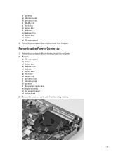
.... 45 f) palmrest g) thermal module h) processor door i) WLAN card j) hard drive k) optical drive l) keyboard m) keyboard trim n) bottom door o) battery p) SD memory card 4. Follow the procedures in After Working Inside Your Computer. Remove: a) SD memory card b) battery c) bottom door d) keyboard trim e) keyboard f) optical drive g) hard drive h) WLAN card i) processor door j) thermal module k) palmrest l) ExpressCard...
.... 45 f) palmrest g) thermal module h) processor door i) WLAN card j) hard drive k) optical drive l) keyboard m) keyboard trim n) bottom door o) battery p) SD memory card 4. Follow the procedures in After Working Inside Your Computer. Remove: a) SD memory card b) battery c) bottom door d) keyboard trim e) keyboard f) optical drive g) hard drive h) WLAN card i) processor door j) thermal module k) palmrest l) ExpressCard...


