Dell Latitude E5530 Support Question
Dell Latitude E5530 Support Question
Find answers below for this question about Dell Latitude E5530.Need a Dell Latitude E5530 manual? We have 3 online manuals for this item!
Question posted by Kikithetos on March 14th, 2014
How To Remove Hard Drive From Dell Latitude E5530
The person who posted this question about this Dell product did not include a detailed explanation. Please use the "Request More Information" button to the right if more details would help you to answer this question.
Current Answers
Related Dell Latitude E5530 Manual Pages
Setup and Features Information Tech Sheet - Page 1
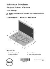
...1. camera (optional) 4. Front And Back View
Figure 1. display release latch
3. microphone (optional) 2. Dell Latitude E5430/E5530
Setup and Features Information
About Warnings
WARNING: A WARNING indicates a potential for property damage, personal injury, or death. camera status light (optional)
Regulatory Model: P27G, P28G Regulatory Type: P27G001, P28G001
2011 - 09 Latitude E5430 -
Setup and Features Information Tech Sheet - Page 3
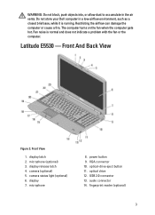
microphone (optional) 3. camera (optional) 5. optical drive 12. fingerprint reader (optional)
3 Restricting the airflow can damage the computer or cause a fire. Latitude E5530 - power button 9. audio connector 14. Do not store your Dell computer in the air vents. Front View
1. USB 2.0 connector 13. WARNING: Do not block, push objects into, or allow dust to accumulate in...
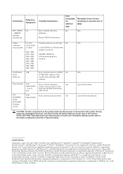
Statement of Volatility - Page 1
...
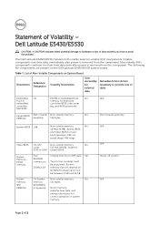
Stores memory, manufacturer data, and
timing information for basic
boot operation, PSA (on the Dell Latitude E5430/E5530 system board.
Dell Latitude E5430/E5530
CAUTION: A CAUTION indicates either potential damage to retain their data immediately after power is removed from the component.
Four SODIMM connectors:
JDIM1,2,3,4
Volatile memory in embedded controller MEC5035
192 KB...
Statement of Volatility - Page 2
... Dell™, the DELL logo, Dell Precision™, OptiPlex™, Latitude...Hard drive(s)
User replaceable - CDROM/RW/ DVD/ DVD+RW/ Diskette Drives
User replaceable
Volatile memory in GB. Non-volatile magnetic
Yes
media, various sizes in off state. Yes
N/A
N/A Low-level format Low-level format/erase
CAUTION: All other countries. Primary power loss (unplugging the power cord and removing...
User Manual - Page 2
... the Keyboard Trim...13 Installing the Keyboard Trim...14 Removing the Keyboard...14 Installing the Keyboard...17 Removing the Bottom Door...18 Installing the Bottom Door...19 Removing the Optical Drive...19 Installing the Optical Drive...21 Removing The Hard Drive...21 Installing the Hard Drive...23 Removing the Wireless Local Area Network (WLAN) Card 24 Installing the Wireless Local Area...
User Manual - Page 21

... the screw that secure the optical drive bracket. 4. Install :
a) bottom door b) battery 7. Remove:
21 Disengage the optical drive bezel tabs to the optical drive. 2. Install the optical drive bracket. 3. Figure 18. 6. Installing the Optical Drive
1. Follow the procedures in Before Working Inside Your Computer. 2. Removing The Hard Drive
1. Remove the screws that secure the...
User Manual - Page 22

Figure 19. 4.
Remove the screws that secure the hard drive bracket in place. Remove the hard drive from its connector. Use the tab to pull the hard drive bracket and release the hard drive from the computer.
22 Figure 20. 5. a) battery b) bottom door 3.
User Manual - Page 23
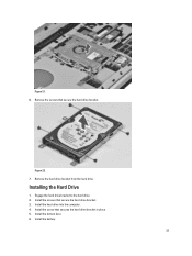
Installing the Hard Drive
1. Install the screw that secure the hard drive bracket. Remove the screws that secures the hard drive bracket in place. 5. Figure 22. 7. Remove the hard drive bracket from the hard drive. Engage the hard drive bracket to the hard drive. 2. Install the screws that secure the hard drive bracket. 3. Install the hard drive into the computer. 4. Install the battery.
23...
User Manual - Page 28
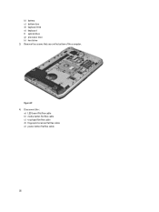
Disconnect the :
a) LED board flat flex cable b) media button flat flex cable c) touchpad flat flex cable d) fingerprint scanner flat flex cable e) power button flat flex cable
28 b) battery c) bottom door d) keyboard trim e) keyboard f) optical drive g) processor door h) hard drive 3. Figure 27. 4. Remove the screws that secure the bottom of the computer.
User Manual - Page 33
... board in Before Working Inside Your Computer.
2. Follow the procedures in the computer.
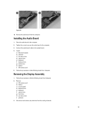
2. Removing the Display Assembly
1. Connect the audio board cable to the computer.
3. Remove: a) SD memory card b) battery c) access panel d) keyboard trim e) keyboard f) optical drive g) hard drive h) processor door i) palmrest
3. Installing the Audio Board
1. Tighten the screw to secure the...
User Manual - Page 36
... in place. 2. Install :
a) palmrest b) processor door c) optical drive d) keyboard e) keyboard trim f) bottom door g) battery h) SD memory card 6. Follow the procedures in Before Working Inside Your Computer. 2. Remove:
a) SD memory card b) battery c) bottom door d) keyboard trim e) optical drive f) hard drive g) processor door h) palmrest i) display assembly 3.
Connect the antenna...
User Manual - Page 37
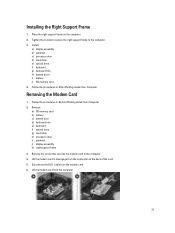
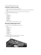
... on the computer. 2. Installing the Right Support Frame
1. Place the right support frame on the back of the card. 5. Removing the Modem Card
1. Remove:
a) SD memory card b) battery c) bottom door d) keyboard trim e) keyboard f) optical drive g) hard drive h) processor door i) palmrest j) display assembly k) right support frame
3. Install:
a) display assembly b) palmrest c) processor door...
User Manual - Page 38
.... 2. Connect the RJ11 cable to the computer. 4. Follow the procedures in Before Working Inside Your Computer. 2.
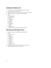
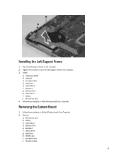
Removing the Left Support Frame
1. Remove:
a) SD memory card b) battery c) bottom door d) keyboard trim e) keyboard f) optical drive g) hard drive h) processor door i) palmrest j) display assembly 3. Lift the left support frame to the modem card. 3. Installing the...
User Manual - Page 39
.... 2. Follow the procedures in After Working Inside Your Computer. Remove:
a) SD memory card b) battery c) bottom door d) keyboard trim e) keyboard f) optical drive g) hard drive h) WLAN card i) processor door j) thermal module
39 Install:
a) display assembly b) palmrest c) processor door d) hard drive e) optical drive f) keyboard g) keyboard trim h) bottom door i) battery j) SD memory card...
User Manual - Page 43
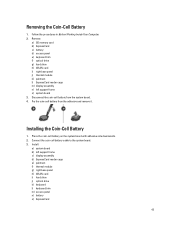
... battery on the system board with adhesive side downwards. 2. Follow the procedures in Before Working Inside Your Computer. 2. Remove:
a) SD memory card b) ExpressCard c) battery d) access panel e) keyboard trim f) optical drive g) hard drive h) WLAN card i) right base panel j) thermal module k) palmrest l) ExpressCard reader cage m) display assembly n) left support frame c) display assembly...
User Manual - Page 44
...
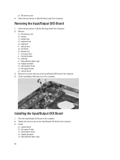
a) SD memory card b) battery c) bottom door d) keyboard trim e) keyboard f) optical drive g) hard drive h) WLAN card i) processor door j) thermal module k) palmrest l) ExpressCard reader cage m) display assembly n) right support frame o) left support frame c) right support frame d) display assembly e) ExpressCard reader cage
44 Remove the screws that secure the Input/Output (I/O) board in the...
User Manual - Page 45
... Working Inside Your Computer. f) palmrest g) thermal module h) processor door i) WLAN card j) hard drive k) optical drive l) keyboard m) keyboard trim n) bottom door o) battery p) SD memory card 4.
Remove:
a) SD memory card b) battery c) bottom door d) keyboard trim e) keyboard f) optical drive g) hard drive h) WLAN card i) processor door j) thermal module k) palmrest l) ExpressCard reader cage...
User Manual - Page 46
... cable in After Working Inside Your Computer. Install:
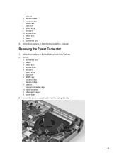
a) system board b) left support bracket c) display assembly d) ExpressCard reader cage e) palmrest f) thermal module g) processor door h) WLAN card i) hard drive j) optical drive k) keyboard l) keyboard trim m) bottom door n) battery o) SD memory card 4. 4.
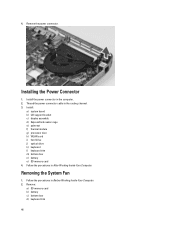
Remove the power connector.
User Manual - Page 47

... the system fan cable from the computer.
47 Remove the screw that secures the system fan and lift it to remove from the routing channel.
4. e) keyboard f) optical drive g) hard drive h) WLAN card i) processor door j) thermal module k) palmrest l) ExpressCard reader cage m) display assembly n) right support frame o) left support frame p) modem card q) network connector r) system board s) power...
User Manual - Page 61
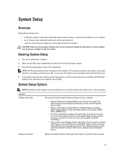
... type of hard drive installed. This prompt can cause your computer to appear. 3. System Setup Options
NOTE: Depending on (or restart) your computer. • set or change , or remove any hardware ... listed in your computer. 2. Once the F2 prompt appears, press immediately.
When the blue DELL logo is displayed, you must watch for it to :
• change the system configuration ...
Similar Questions

What Is The Sm Bus Controller Dell Latitude E5530 Windows 7
(Posted by tidm 9 years ago)

How To Make The Hard Drive Removable On A Dell E5530
(Posted by beDave 9 years ago)


