View
Page 2
... you ordered your computer with an optional discrete graphics card, connect the display to the port on your discrete graphics card 4 Connect the power cable and press the power button 5 Complete Windows setup 完成 Windows Windows 設定 Windows Windows Record your Windows password here NOTE: Do not use the @ symbol...
... you ordered your computer with an optional discrete graphics card, connect the display to the port on your discrete graphics card 4 Connect the power cable and press the power button 5 Complete Windows setup 完成 Windows Windows 設定 Windows Windows Record your Windows password here NOTE: Do not use the @ symbol...
Owners Manual
Page 5
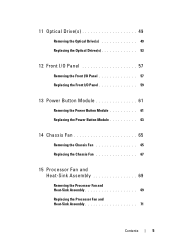
11 Optical Drive(s 49 Removing the Optical Drive(s 49 Replacing the Optical Drives(s 53 12 Front I/O Panel 57 Removing the Front I/O Panel 57 Replacing the Front I/O Panel 59 13 Power Button Module 61 Removing the Power Button Module 61 Replacing the Power Button Module 63 14 Chassis Fan 65 Removing the Chassis Fan 65 Replacing the Chassis Fan 67 15 Processor Fan and Heat-Sink Assembly 69 Removing the Processor Fan and Heat-Sink Assembly 69 Replacing the Processor Fan and Heat-Sink Assembly 71 Contents 5
11 Optical Drive(s 49 Removing the Optical Drive(s 49 Replacing the Optical Drives(s 53 12 Front I/O Panel 57 Removing the Front I/O Panel 57 Replacing the Front I/O Panel 59 13 Power Button Module 61 Removing the Power Button Module 61 Replacing the Power Button Module 63 14 Chassis Fan 65 Removing the Chassis Fan 65 Replacing the Chassis Fan 67 15 Processor Fan and Heat-Sink Assembly 69 Removing the Processor Fan and Heat-Sink Assembly 69 Replacing the Processor Fan and Heat-Sink Assembly 71 Contents 5
Owners Manual
Page 6
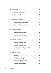
16 Processor 73 Removing the Processor 73 Replacing the Processor 75 17 Coin-Cell Battery 77 Removing the Coin-Cell Battery 77 Replacing the Coin-Cell Battery 79 18 Power Supply 81 Removing the Power Supply 81 Replacing the Power Supply 83 19 System Board 85 Removing the System Board 85 Replacing the System Board 87 Entering the Service Tag in the BIOS 88 20 System Setup 91 Overview 91 Entering System Setup 91 Clearing Forgotten Passwords 102 Clearing CMOS Passwords 104 6 Contents
16 Processor 73 Removing the Processor 73 Replacing the Processor 75 17 Coin-Cell Battery 77 Removing the Coin-Cell Battery 77 Replacing the Coin-Cell Battery 79 18 Power Supply 81 Removing the Power Supply 81 Replacing the Power Supply 83 19 System Board 85 Removing the System Board 85 Replacing the System Board 87 Entering the Service Tag in the BIOS 88 20 System Setup 91 Overview 91 Entering System Setup 91 Clearing Forgotten Passwords 102 Clearing CMOS Passwords 104 6 Contents
Owners Manual
Page 9
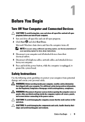
... 3 Disconnect your computer and all telephone cables, network cables, and attached devices from your computer. 5 Press and hold the power button, while the computer is flat and clean. For additional safety best practices information, see the documentation of your operating system...programs before you turn off . Safety Instructions Use the following safety guidelines to the power source. After you are using a different operating system, see the Regulatory Compliance Homepage at dell.com/regulatory_compliance. Before You Begin 9 NOTE: If you finish working inside the computer...
... 3 Disconnect your computer and all telephone cables, network cables, and attached devices from your computer. 5 Press and hold the power button, while the computer is flat and clean. For additional safety best practices information, see the documentation of your operating system...programs before you turn off . Safety Instructions Use the following safety guidelines to the power source. After you are using a different operating system, see the Regulatory Compliance Homepage at dell.com/regulatory_compliance. Before You Begin 9 NOTE: If you finish working inside the computer...
Owners Manual
Page 13
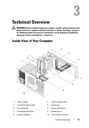
For additional safety best practices information, see the Regulatory Compliance Homepage at dell.com/regulatory_compliance. Inside View of Your Computer 3 2 1 4 5 6 10 1 power supply 3 secondary optical-drive 5 front I/O panel 7 secondary hard-drive 9 memory modules 7 8 9 2 primary optical-drive 4 front bezel 6 primary hard-drive 8 system board 10 card retention bracket Technical Overview 13 Technical Overview WARNING: Before working inside your computer, read the safety information that shipped with your computer and follow the steps in "Before You Begin" on page 9.
For additional safety best practices information, see the Regulatory Compliance Homepage at dell.com/regulatory_compliance. Inside View of Your Computer 3 2 1 4 5 6 10 1 power supply 3 secondary optical-drive 5 front I/O panel 7 secondary hard-drive 9 memory modules 7 8 9 2 primary optical-drive 4 front bezel 6 primary hard-drive 8 system board 10 card retention bracket Technical Overview 13 Technical Overview WARNING: Before working inside your computer, read the safety information that shipped with your computer and follow the steps in "Before You Begin" on page 9.
Owners Manual
Page 44
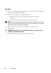
...drive. 4 Lift the hard-drive assembly away from the primary and secondary hard-drives. Procedure 1 If you are removing the primary hard-drive, disconnect the power and data cables from the primary hard-drive. 2 If you are not replacing the hard drive at a later time. 3 Remove the screws that you are... removing the secondary hard-drive: a Disconnect the power cable from the computer. 44 Hard Drive(s) You can use the data cable to install a hard drive at this time, disconnect the other end of...
...drive. 4 Lift the hard-drive assembly away from the primary and secondary hard-drives. Procedure 1 If you are removing the primary hard-drive, disconnect the power and data cables from the primary hard-drive. 2 If you are not replacing the hard drive at a later time. 3 Remove the screws that you are... removing the secondary hard-drive: a Disconnect the power cable from the computer. 44 Hard Drive(s) You can use the data cable to install a hard drive at this time, disconnect the other end of...
Owners Manual
Page 48
... assembly to the hard-drive bay. 5 If you are replacing the primary hard-drive, connect the power and data cables to the primary hard drive. 6 If you are replacing the secondary hard-drive: a Connect the power cable to the secondary hard-drive. b Connect the data cable to the primary and secondary hard...
... assembly to the hard-drive bay. 5 If you are replacing the primary hard-drive, connect the power and data cables to the primary hard drive. 6 If you are replacing the secondary hard-drive: a Connect the power cable to the secondary hard-drive. b Connect the data cable to the primary and secondary hard...

Owners Manual
Page 50
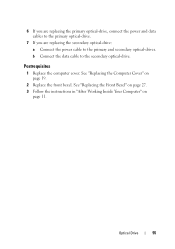
... connector and set it aside. Procedure 1 If you are removing the primary optical-drive, disconnect the power and data cables from the primary optical-drive. 2 If you are removing the secondary optical-drive: a Disconnect the power cable from the secondary optical-drive. NOTE: If you are not replacing the optical drive at...
... connector and set it aside. Procedure 1 If you are removing the primary optical-drive, disconnect the power and data cables from the primary optical-drive. 2 If you are removing the secondary optical-drive: a Disconnect the power cable from the secondary optical-drive. NOTE: If you are not replacing the optical drive at...
Owners Manual
Page 52
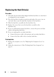
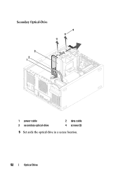
Secondary Optical-Drive 4 3 2 1 1 power cable 3 secondary optical-drive 2 data cable 4 screws (2) 5 Set aside the optical drive in a secure location. 52 Optical Drive
Secondary Optical-Drive 4 3 2 1 1 power cable 3 secondary optical-drive 2 data cable 4 screws (2) 5 Set aside the optical drive in a secure location. 52 Optical Drive
Owners Manual
Page 55
Postrequisites 1 Replace the computer cover. See "Replacing the Computer Cover" on page 11. b Connect the data cable to the primary and secondary optical-drives. Optical Drive 55 6 If you are replacing the primary optical-drive, connect the power and data cables to the primary optical-drive. 7 If you are replacing the secondary optical-drive: a Connect the power cable to the secondary optical-drive. See "Replacing the Front Bezel" on page 27. 3 Follow the instructions in "After Working Inside Your Computer" on page 19. 2 Replace the front bezel.
Postrequisites 1 Replace the computer cover. See "Replacing the Computer Cover" on page 11. b Connect the data cable to the primary and secondary optical-drives. Optical Drive 55 6 If you are replacing the primary optical-drive, connect the power and data cables to the primary optical-drive. 7 If you are replacing the secondary optical-drive: a Connect the power cable to the secondary optical-drive. See "Replacing the Front Bezel" on page 27. 3 Follow the instructions in "After Working Inside Your Computer" on page 19. 2 Replace the front bezel.
Owners Manual
Page 61
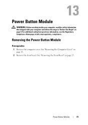
For additional safety best practices information, see the Regulatory Compliance Homepage at dell.com/regulatory_compliance. Removing the Power Button Module Prerequisites 1 Remove the computer cover. Power Button Module WARNING: Before working inside your computer, read the safety information that shipped with your computer and follow the steps in "Before You Begin" on page 25. Power Button Module 61 See "Removing the Front Bezel" on page 9. See "Removing the Computer Cover" on page 18. 2 Remove the front bezel.
For additional safety best practices information, see the Regulatory Compliance Homepage at dell.com/regulatory_compliance. Removing the Power Button Module Prerequisites 1 Remove the computer cover. Power Button Module WARNING: Before working inside your computer, read the safety information that shipped with your computer and follow the steps in "Before You Begin" on page 25. Power Button Module 61 See "Removing the Front Bezel" on page 9. See "Removing the Computer Cover" on page 18. 2 Remove the front bezel.
Owners Manual
Page 62
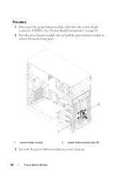
Procedure 1 Disconnect the power button module cable from the front panel. 2 1 1 power button module 2 power button module tabs (4) 3 Set aside the power button module in a secure location. 62 Power Button Module See "System Board Components" on page 14. 2 Press the power button module tabs and pull the power button module to release it from the system board connector (LEDH2).
Procedure 1 Disconnect the power button module cable from the front panel. 2 1 1 power button module 2 power button module tabs (4) 3 Set aside the power button module in a secure location. 62 Power Button Module See "System Board Components" on page 14. 2 Press the power button module tabs and pull the power button module to release it from the system board connector (LEDH2).
Owners Manual
Page 63
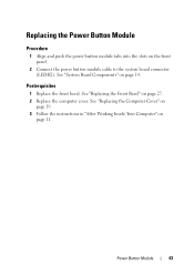
Replacing the Power Button Module Procedure 1 Align and push the power button module tabs into the slots on page 27. 2 Replace the computer cover. See "Replacing the Front Bezel" on the front panel. 2 Connect the power button module cable to the system board connector (LEDH2). See "System Board Components" on page 11. Power Button Module 63 See "Replacing the Computer Cover" on page 19. 3 Follow the instructions in "After Working Inside Your Computer" on page 14. Postrequisites 1 Replace the front bezel.
Replacing the Power Button Module Procedure 1 Align and push the power button module tabs into the slots on page 27. 2 Replace the computer cover. See "Replacing the Front Bezel" on the front panel. 2 Connect the power button module cable to the system board connector (LEDH2). See "System Board Components" on page 11. Power Button Module 63 See "Replacing the Computer Cover" on page 19. 3 Follow the instructions in "After Working Inside Your Computer" on page 14. Postrequisites 1 Replace the front bezel.
Owners Manual
Page 81
See "Removing the Computer Cover" on page 9. Power Supply 81 Power Supply WARNING: Before working inside your computer, read the safety information that shipped with your computer and follow the steps in "Before You Begin" on page 18. For additional safety best practices information, see the Regulatory Compliance Homepage at dell.com/regulatory_compliance. Removing the Power Supply Prerequisites Remove the computer cover.
See "Removing the Computer Cover" on page 9. Power Supply 81 Power Supply WARNING: Before working inside your computer, read the safety information that shipped with your computer and follow the steps in "Before You Begin" on page 18. For additional safety best practices information, see the Regulatory Compliance Homepage at dell.com/regulatory_compliance. Removing the Power Supply Prerequisites Remove the computer cover.
Owners Manual
Page 82
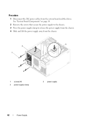
See "System Board Components" on page 14. 2 Remove the screws that secure the power supply to the chassis. 3 Press the power supply clamp to release the power supply from the chassis. 4 Slide and lift the power supply away from the system board and the drives. Procedure 1 Disconnect the DC power cables from the chassis. 3 2 1 1 screws (4) 3 power supply clamp 2 power supply 82 Power Supply
See "System Board Components" on page 14. 2 Remove the screws that secure the power supply to the chassis. 3 Press the power supply clamp to release the power supply from the chassis. 4 Slide and lift the power supply away from the system board and the drives. Procedure 1 Disconnect the DC power cables from the chassis. 3 2 1 1 screws (4) 3 power supply clamp 2 power supply 82 Power Supply
Owners Manual
Page 83
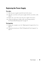
Replacing the Power Supply Procedure 1 Slide the power supply towards the back of the chassis. 2 Align the screw holes on the power supply with the screw holes on page 11. See "Replacing the Computer Cover" on page 19. 2 Follow the instructions in "After Working Inside Your Computer" on the chassis. 3 Replace the screws that secure the power supply to the chassis. 4 Connect the DC power cables to the system board and drives. Power Supply 83 See "System Board Components" on page 14. Postrequisites 1 Replace the computer cover.
Replacing the Power Supply Procedure 1 Slide the power supply towards the back of the chassis. 2 Align the screw holes on the power supply with the screw holes on page 11. See "Replacing the Computer Cover" on page 19. 2 Follow the instructions in "After Working Inside Your Computer" on the chassis. 3 Replace the screws that secure the power supply to the chassis. 4 Connect the DC power cables to the system board and drives. Power Supply 83 See "System Board Components" on page 14. Postrequisites 1 Replace the computer cover.
Owners Manual
Page 92
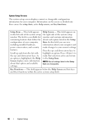
... setup field. 92 System Setup This field appears on the screen is highlighted, the Help Screen displays more information about your computer, including installed hardware, power conservation, and security features. Scroll up - and down-arrow keys to your computer.
... setup field. 92 System Setup This field appears on the screen is highlighted, the Help Screen displays more information about your computer, including installed hardware, power conservation, and security features. Scroll up - and down-arrow keys to your computer.
Owners Manual
Page 97
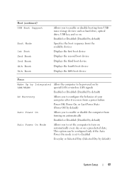
... (Disabled by default) AC Recovery Allows you to configure the behavior of your computer after it recovers from a power failure Power Off, Power On, or Last Power State (Power Off by default) Auto Power On Allows you to set to turn on automatically every day or on . Boot (continued) USB Boot Support ...3rd Boot 4th Boot 5th Boot Allows you to enable or disable booting from turning on automatically Enabled or Disabled (Disabled by default) Auto Power On Mode Allows you to enable or disable the computer from USB mass storage devices such as hard drive, optical drive, USB key,...
... (Disabled by default) AC Recovery Allows you to configure the behavior of your computer after it recovers from a power failure Power Off, Power On, or Last Power State (Power Off by default) Auto Power On Allows you to set to turn on automatically every day or on . Boot (continued) USB Boot Support ...3rd Boot 4th Boot 5th Boot Allows you to enable or disable booting from turning on automatically Enabled or Disabled (Disabled by default) Auto Power On Mode Allows you to enable or disable the computer from USB mass storage devices such as hard drive, optical drive, USB key,...
Owners Manual
Page 98
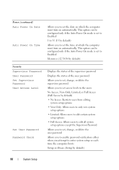
... Time Allows you to 31 (15 by default) 98 System Setup This option can be configured only if the Auto Power On mode is set to Enabled hh:mm:ss (12:30:30 by default) Security Supervisor Password User Password Set Supervisor Password User Access Level ... by default) Allows you to set the time at which the computer must turn on automatically; This option can be configured only if the Auto Power On mode is set to Enabled 1 to set the date on which the computer must turn on automatically;
... Time Allows you to 31 (15 by default) 98 System Setup This option can be configured only if the Auto Power On mode is set to Enabled hh:mm:ss (12:30:30 by default) Security Supervisor Password User Password Set Supervisor Password User Access Level ... by default) Allows you to set the time at which the computer must turn on automatically; This option can be configured only if the Auto Power On mode is set to Enabled 1 to set the date on which the computer must turn on automatically;


