
Owners Manual
Page 3
Contents 1 Before You Begin 9 Turn Off Your Computer and Connected Devices . . . . . 9 Safety Instructions 9 Recommended Tools 10 2 After Working Inside Your Computer . . . 11 3 Technical Overview 13 Inside View of Your Computer 13 System Board Components 14 4 Computer Cover 17 Removing the Computer Cover 18 Replacing the Computer Cover 19 5 Memory Module(s 21 Removing the Memory Module(s 21 Replacing the Memory Module(s 22 Contents 3
Contents 1 Before You Begin 9 Turn Off Your Computer and Connected Devices . . . . . 9 Safety Instructions 9 Recommended Tools 10 2 After Working Inside Your Computer . . . 11 3 Technical Overview 13 Inside View of Your Computer 13 System Board Components 14 4 Computer Cover 17 Removing the Computer Cover 18 Replacing the Computer Cover 19 5 Memory Module(s 21 Removing the Memory Module(s 21 Replacing the Memory Module(s 22 Contents 3
Owners Manual
Page 13
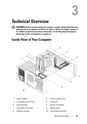
For additional safety best practices information, see the Regulatory Compliance Homepage at dell.com/regulatory_compliance. Inside View of Your Computer 3 2 1 4 5 6 10 1 power supply 3 secondary optical-drive 5 front I/O panel 7 secondary hard-drive 9 memory modules 7 8 9 2 primary optical-drive 4 front bezel 6 primary hard-drive 8 system board 10 card retention bracket Technical Overview 13 Technical Overview WARNING: Before working inside your computer, read the safety information that shipped with your computer and follow the steps in "Before You Begin" on page 9.
For additional safety best practices information, see the Regulatory Compliance Homepage at dell.com/regulatory_compliance. Inside View of Your Computer 3 2 1 4 5 6 10 1 power supply 3 secondary optical-drive 5 front I/O panel 7 secondary hard-drive 9 memory modules 7 8 9 2 primary optical-drive 4 front bezel 6 primary hard-drive 8 system board 10 card retention bracket Technical Overview 13 Technical Overview WARNING: Before working inside your computer, read the safety information that shipped with your computer and follow the steps in "Before You Begin" on page 9.
Owners Manual
Page 21
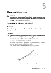
... back and forth to cool before touching them. 1 Locate the memory-module connector on page 14. 2 Press out the securing clip at dell.com/regulatory_compliance. Procedure WARNING: The memory module(s) may become very hot during normal operation. Allow the memory module(s) to remove it upwards. For additional safety best practices information, see the Regulatory...
... back and forth to cool before touching them. 1 Locate the memory-module connector on page 14. 2 Press out the securing clip at dell.com/regulatory_compliance. Procedure WARNING: The memory module(s) may become very hot during normal operation. Allow the memory module(s) to remove it upwards. For additional safety best practices information, see the Regulatory...
Owners Manual
Page 22
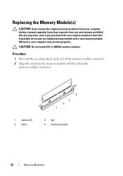
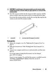
... out the securing clip at each end of the memory module connector. 2 Align the notch on the memory module with a new memory module. Otherwise, your computer during a memory upgrade, keep them separate from Dell. If possible, do not pair an original memory module with the tab in the memory module connector. 1 cutouts (2) 3 notch 4 3 2 1 2 tab 4 memory module 22 Memory Module(s)
... out the securing clip at each end of the memory module connector. 2 Align the notch on the memory module with a new memory module. Otherwise, your computer during a memory upgrade, keep them separate from Dell. If possible, do not pair an original memory module with the tab in the memory module connector. 1 cutouts (2) 3 notch 4 3 2 1 2 tab 4 memory module 22 Memory Module(s)
Owners Manual
Page 23
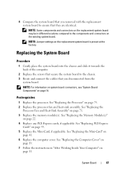
... Check the amount of the memory module. 2 1 1 cutouts (2) 2 securing clips (2) (snapped in position) Postrequisites 1 Replace the computer cover. If you apply equal force to each end of the memory module. 3 Insert the memory module into the memory-module connector until the memory module snaps into the cutouts... at each end of memory (RAM) listed. To verify that the memory size has changed, press to continue. See "...
... Check the amount of the memory module. 2 1 1 cutouts (2) 2 securing clips (2) (snapped in position) Postrequisites 1 Replace the computer cover. If you apply equal force to each end of the memory module. 3 Insert the memory module into the memory-module connector until the memory module snaps into the cutouts... at each end of memory (RAM) listed. To verify that the memory size has changed, press to continue. See "...

Owners Manual
Page 24
24 Memory Module(s)
24 Memory Module(s)

Owners Manual
Page 85
...Remove the processor fan and heat-sink assembly. System Board 85 See "Removing the Mini-Card" on page 21. See "Removing the Memory Module(s)" on page 40. 3 Remove the any PCI-Express cards, if applicable. For additional safety best practices information, see the Regulatory ...Compliance Homepage at dell.com/regulatory_compliance. Record which memory module is removed from each DIMM slot so that shipped with your computer, read the safety information that the memory modules can be installed in "Before You Begin" on page 9....
...Remove the processor fan and heat-sink assembly. System Board 85 See "Removing the Mini-Card" on page 21. See "Removing the Memory Module(s)" on page 40. 3 Remove the any PCI-Express cards, if applicable. For additional safety best practices information, see the Regulatory ...Compliance Homepage at dell.com/regulatory_compliance. Record which memory module is removed from each DIMM slot so that shipped with your computer, read the safety information that the memory modules can be installed in "Before You Begin" on page 9....
Owners Manual
Page 87
... Processor Fan and Heat-Sink Assembly" on page 41. 6 Replace the computer cover. See "Replacing the Mini-Card" on page 71. 3 Replace the memory module(s). See "Replacing the Memory Module(s)" on page 14. System Board 87 NOTE: For information on system board connectors, see "System Board Components" on page 22. 4 Replace any...
... Processor Fan and Heat-Sink Assembly" on page 41. 6 Replace the computer cover. See "Replacing the Mini-Card" on page 71. 3 Replace the memory module(s). See "Replacing the Memory Module(s)" on page 14. System Board 87 NOTE: For information on system board connectors, see "System Board Components" on page 22. 4 Replace any...
Owners Manual
Page 93
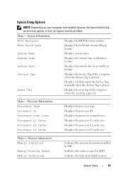
...cache size Displays the processor L2 cache size Displays the processor L3 cache size Main - Memory Information Memory Installed Memory Running Speed Memory Technology Indicates the amount of memory installed in MB Indicates the memory speed in this section may appear, or may not appear exactly as listed. Main -... System Setup Options NOTE: Depending on your computer and installed devices, the items listed in MHz Indicates the type of installed memory System Setup 93 System Information BIOS Revision Displays the BIOS Revision number BIOS Build Date Displays the build date in mm/dd/...
...cache size Displays the processor L2 cache size Displays the processor L3 cache size Main - Memory Information Memory Installed Memory Running Speed Memory Technology Indicates the amount of memory installed in MB Indicates the memory speed in this section may appear, or may not appear exactly as listed. Main -... System Setup Options NOTE: Depending on your computer and installed devices, the items listed in MHz Indicates the type of installed memory System Setup 93 System Information BIOS Revision Displays the BIOS Revision number BIOS Build Date Displays the build date in mm/dd/...

Owners Manual
Page 100
... from the network, ensure that your device is on the drive, the computer generates an error message. • CD/DVD/CD-RW Drive - Insert the memory device into a USB port and restart the computer. The BIOS detects the device and adds the USB flash option to change the boot sequence for...
... from the network, ensure that your device is on the drive, the computer generates an error message. • CD/DVD/CD-RW Drive - Insert the memory device into a USB port and restart the computer. The BIOS detects the device and adds the USB flash option to change the boot sequence for...

Owners Manual
Page 101
To ensure your computer. 3 When F2 Setup, F12 Boot Options appears in case you are booting to a USB memory key, highlight USB Storage Device and press . For example, if you are booting from a USB device, connect the USB device to a USB port. 2 Turn on ... Boot menu option and press to access the menu. Changing Boot Sequence for example, to boot from the CD/DVD/CD-RW drive to run Dell Diagnostics from . System Setup 101 Then, shut down your current boot sequence in the lower-right corner of the screen, press . The Boot Device Menu...
To ensure your computer. 3 When F2 Setup, F12 Boot Options appears in case you are booting to a USB memory key, highlight USB Storage Device and press . For example, if you are booting from a USB device, connect the USB device to a USB port. 2 Turn on ... Boot menu option and press to access the menu. Changing Boot Sequence for example, to boot from the CD/DVD/CD-RW drive to run Dell Diagnostics from . System Setup 101 Then, shut down your current boot sequence in the lower-right corner of the screen, press . The Boot Device Menu...


