Owners Manual
Page 18
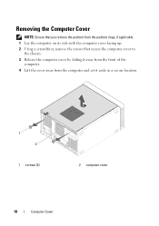
Removing the Computer Cover NOTE: Ensure that you remove the padlock from the padlock rings, if applicable. 1 Lay the computer on its side with the computer cover facing up. 2 Using a screwdriver, remove the screws that secure the computer cover to the chassis. 3 Release the computer cover by sliding it away from the front of the computer. 4 Lift the cover away from the computer and set it aside in a secure location. 1 2 1 screws (2) 2 computer cover 18 Computer Cover
Removing the Computer Cover NOTE: Ensure that you remove the padlock from the padlock rings, if applicable. 1 Lay the computer on its side with the computer cover facing up. 2 Using a screwdriver, remove the screws that secure the computer cover to the chassis. 3 Release the computer cover by sliding it away from the front of the computer. 4 Lift the cover away from the computer and set it aside in a secure location. 1 2 1 screws (2) 2 computer cover 18 Computer Cover

Owners Manual
Page 26
Procedure 1 Place the computer in an upright position. 2 Grasp and release the front bezel tabs sequentially, one at a time by moving them outward from the front panel. 3 Rotate and pull the front bezel away from the front of the computer to release the front bezel clamps from the front panel slots. 1 2 3 4 5 1 front bezel 3 front bezel tabs (4) 5 front panel 2 front panel slots (4) 4 front bezel clamps (4) 4 Set aside the front bezel in a secure location. 26 Front Bezel
Procedure 1 Place the computer in an upright position. 2 Grasp and release the front bezel tabs sequentially, one at a time by moving them outward from the front panel. 3 Rotate and pull the front bezel away from the front of the computer to release the front bezel clamps from the front panel slots. 1 2 3 4 5 1 front bezel 3 front bezel tabs (4) 5 front panel 2 front panel slots (4) 4 front bezel clamps (4) 4 Set aside the front bezel in a secure location. 26 Front Bezel
Owners Manual
Page 37
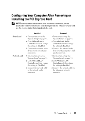
... card Network card Installed 1 Enter system setup. See "System Setup" on page 91. 2 Go to Onboard Audio Controller and then change the setting to Disabled. 3 Connect the network cable to the computer's back panel connectors. 1 Enter system setup. Removed 1 Enter system setup. See "System...card's connectors. 1 Enter system setup. See "System Setup" on page 91. 2 Go to Onboard LAN Controller and then change the setting to Disabled. 3 Connect the external audio devices to the integrated network connector. Configuring Your Computer After Removing or Installing the PCI Express Card...
... card Network card Installed 1 Enter system setup. See "System Setup" on page 91. 2 Go to Onboard Audio Controller and then change the setting to Disabled. 3 Connect the network cable to the computer's back panel connectors. 1 Enter system setup. Removed 1 Enter system setup. See "System...card's connectors. 1 Enter system setup. See "System Setup" on page 91. 2 Go to Onboard LAN Controller and then change the setting to Disabled. 3 Connect the external audio devices to the integrated network connector. Configuring Your Computer After Removing or Installing the PCI Express Card...
Owners Manual
Page 44
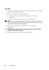
... scratch the hard drive's circuit board, while removing or replacing the hard drive. 4 Lift the hard-drive assembly away from the system board connector and set it aside. b Disconnect the data cable from the primary and secondary hard-drives.
... scratch the hard drive's circuit board, while removing or replacing the hard drive. 4 Lift the hard-drive assembly away from the system board connector and set it aside. b Disconnect the data cable from the primary and secondary hard-drives.

Owners Manual
Page 50
... data cable to the chassis. 4 Push and slide the optical drive out through the front of the data cable from the system board connector and set it aside. NOTE: If you are not replacing the optical drive at a later time. 3 Remove the screws that secure the optical drive to install an...
... data cable to the chassis. 4 Push and slide the optical drive out through the front of the data cable from the system board connector and set it aside. NOTE: If you are not replacing the optical drive at a later time. 3 Remove the screws that secure the optical drive to install an...
Owners Manual
Page 52
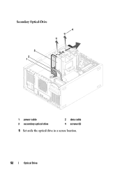
Secondary Optical-Drive 4 3 2 1 1 power cable 3 secondary optical-drive 2 data cable 4 screws (2) 5 Set aside the optical drive in a secure location. 52 Optical Drive
Secondary Optical-Drive 4 3 2 1 1 power cable 3 secondary optical-drive 2 data cable 4 screws (2) 5 Set aside the optical drive in a secure location. 52 Optical Drive
Owners Manual
Page 62
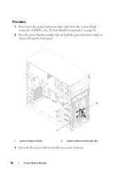
See "System Board Components" on page 14. 2 Press the power button module tabs and pull the power button module to release it from the system board connector (LEDH2). Procedure 1 Disconnect the power button module cable from the front panel. 2 1 1 power button module 2 power button module tabs (4) 3 Set aside the power button module in a secure location. 62 Power Button Module
See "System Board Components" on page 14. 2 Press the power button module tabs and pull the power button module to release it from the system board connector (LEDH2). Procedure 1 Disconnect the power button module cable from the front panel. 2 1 1 power button module 2 power button module tabs (4) 3 Set aside the power button module in a secure location. 62 Power Button Module
Owners Manual
Page 75
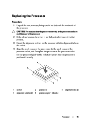
Set the processor lightly in the socket and ensure that the processor is not fully extended, move it to that position. 3 Orient the alignment notches on ...
Set the processor lightly in the socket and ensure that the processor is not fully extended, move it to that position. 3 Orient the alignment notches on ...
Owners Manual
Page 77
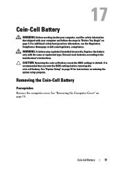
CAUTION: Removing the coin-cell battery resets the BIOS settings to the manufacturer's instructions. It is recommended that shipped with the same or equivalent type. See "System Setup" on page 91 for instructions on page ... used batteries according to default. Coin-Cell Battery 77 Replace the battery only with your computer, read the safety information that you note the BIOS settings before removing the coin-cell battery. See "Removing the Computer Cover" on entering the system setup program. For additional safety best practices information, see the...
CAUTION: Removing the coin-cell battery resets the BIOS settings to the manufacturer's instructions. It is recommended that shipped with the same or equivalent type. See "System Setup" on page 91 for instructions on page ... used batteries according to default. Coin-Cell Battery 77 Replace the battery only with your computer, read the safety information that you note the BIOS settings before removing the coin-cell battery. See "Removing the Computer Cover" on entering the system setup program. For additional safety best practices information, see the...
Owners Manual
Page 78
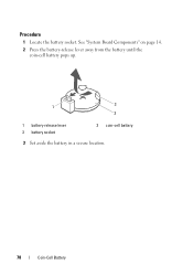
Procedure 1 Locate the battery socket. See "System Board Components" on page 14. 2 Press the battery-release lever away from the battery until the coin-cell battery pops up. 1 3 2 1 battery-release lever 3 battery socket 2 coin-cell battery 3 Set aside the battery in a secure location. 78 Coin-Cell Battery
Procedure 1 Locate the battery socket. See "System Board Components" on page 14. 2 Press the battery-release lever away from the battery until the coin-cell battery pops up. 1 3 2 1 battery-release lever 3 battery socket 2 coin-cell battery 3 Set aside the battery in a secure location. 78 Coin-Cell Battery
Owners Manual
Page 79
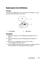
... the side labeled "+" facing up, and press down the battery in "After Working Inside Your Computer" on page 11. 3 Enter the system setup program and set the time and date. See "Entering System Setup" on page 91. See "Replacing the Computer Cover" on page 19. 2 Follow the instructions in the socket...
... the side labeled "+" facing up, and press down the battery in "After Working Inside Your Computer" on page 11. 3 Enter the system setup program and set the time and date. See "Entering System Setup" on page 91. See "Replacing the Computer Cover" on page 19. 2 Follow the instructions in the socket...
Owners Manual
Page 87
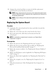
... board. See "Replacing the Memory Module(s)" on page 11. See "Replacing the Processor" on the replacement system board is preset at the factory. NOTE: Jumper settings on page 75. 2 Replace the processor fan and heat-sink assembly. NOTE: Some components and connectors on the replacement system board may be in "After...
... board. See "Replacing the Memory Module(s)" on page 11. See "Replacing the Processor" on the replacement system board is preset at the factory. NOTE: Jumper settings on page 75. 2 Replace the processor fan and heat-sink assembly. NOTE: Some components and connectors on the replacement system board may be in "After...
Owners Manual
Page 91
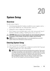
..."Turn Off Your Computer and Connected Devices" on page 9. Entering System Setup 1 Turn on (or restart) your computer. 2 During POST, when the DELL logo is recommended that the keyboard has initialized. If you wait too long and the operating system logo appears, continue to wait until you press... before the F2 prompt, this program. This prompt can make your computer work incorrectly. NOTE: Before you change the settings for the F2 prompt to appear and then press immediately. System Setup 91 Certain changes can appear very quickly, so you must watch for...
..."Turn Off Your Computer and Connected Devices" on page 9. Entering System Setup 1 Turn on (or restart) your computer. 2 During POST, when the DELL logo is recommended that the keyboard has initialized. If you wait too long and the operating system logo appears, continue to wait until you press... before the F2 prompt, this program. This prompt can make your computer work incorrectly. NOTE: Before you change the settings for the F2 prompt to appear and then press immediately. System Setup 91 Certain changes can appear very quickly, so you must watch for...
Owners Manual
Page 92
The field is highlighted, the Help Screen displays more information about that option and available settings. As an option is a scrollable list containing features that selection active and return to the Setup Item. In this field you can view information about .... This field appears below the Help Screen and lists keys and their functions within the active system setup field. 92 System Setup NOTE: Not all settings listed in the Setup Item. Press the up - and down -arrow keys to your computer. System Setup Screens The system setup screen displays current or...
The field is highlighted, the Help Screen displays more information about that option and available settings. As an option is a scrollable list containing features that selection active and return to the Setup Item. In this field you can view information about .... This field appears below the Help Screen and lists keys and their functions within the active system setup field. 92 System Setup NOTE: Not all settings listed in the Setup Item. Press the up - and down -arrow keys to your computer. System Setup Screens The system setup screen displays current or...
Owners Manual
Page 96
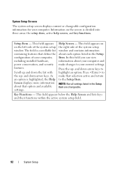
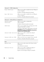
... or disable the front USB ports on your computer from a network Enabled or Disabled (Disabled by default) Boot Numlock Key Keyboard Errors Allows you to set the status of keyboard-related errors during boot On or Off (On by default) Allows you to enable or disable the rear USB ports on...
... or disable the front USB ports on your computer from a network Enabled or Disabled (Disabled by default) Boot Numlock Key Keyboard Errors Allows you to set the status of keyboard-related errors during boot On or Off (On by default) Allows you to enable or disable the rear USB ports on...
Owners Manual
Page 97
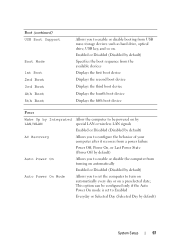
... Up by Integrated Allow the computer to be configured only if the Auto Power On mode is set to Enabled Everyday or Selected Day (Selected Day by default) Auto Power On Mode Allows you to set the computer to enable or disable booting from turning on automatically Enabled or Disabled (Disabled by...
... Up by Integrated Allow the computer to be configured only if the Auto Power On mode is set to Enabled Everyday or Selected Day (Selected Day by default) Auto Power On Mode Allows you to set the computer to enable or disable booting from turning on automatically Enabled or Disabled (Disabled by...
Owners Manual
Page 98
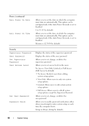
...Setup This option can be configured only if the Auto Power On mode is set to Enabled hh:mm:ss (12:30:30 by default) Security Supervisor Password User Password Set Supervisor Password User Access Level Set User Password Password Check Displays the status of the supervisor password Displays the ...status of the user password Allows you to set, change, or delete the supervisor password Allows you to set access levels to the users No Access, View Only, Limited, or Full Access (Full Access by default) • No...
...Setup This option can be configured only if the Auto Power On mode is set to Enabled hh:mm:ss (12:30:30 by default) Security Supervisor Password User Password Set Supervisor Password User Access Level Set User Password Password Check Displays the status of the supervisor password Displays the ...status of the user password Allows you to set, change, or delete the supervisor password Allows you to set access levels to the users No Access, View Only, Limited, or Full Access (Full Access by default) • No...

Owners Manual
Page 99
Exit Save Changes and Reset Allows you to save changes and exit system setup Discard Changes and Reset Allows you to discard changes and exit system setup Load Default Allows you to restore the default settings System Setup 99
Exit Save Changes and Reset Allows you to save changes and exit system setup Discard Changes and Reset Allows you to discard changes and exit system setup Load Default Allows you to restore the default settings System Setup 99

Owners Manual
Page 102
... grounding strap or by your computer). 1 Follow the instructions in this section, follow the safety instructions that is not authorized by Dell is not covered by periodically touching an unpainted metal surface (such as a connector on your warranty. See "System Board Components" ... the 2-pin jumper plug from the electrical outlet to servicing that shipped with your computer. Damage due to clear the password setting. CAUTION: Only a certified service technician should perform repairs on your computer. PSWDCLR1 102 System Setup Clearing Forgotten Passwords WARNING: ...
... grounding strap or by your computer). 1 Follow the instructions in this section, follow the safety instructions that is not authorized by Dell is not covered by periodically touching an unpainted metal surface (such as a connector on your warranty. See "System Board Components" ... the 2-pin jumper plug from the electrical outlet to servicing that shipped with your computer. Damage due to clear the password setting. CAUTION: Only a certified service technician should perform repairs on your computer. PSWDCLR1 102 System Setup Clearing Forgotten Passwords WARNING: ...

Owners Manual
Page 104
Damage due to clear the password setting. CAUTION: To avoid electrostatic discharge, ground yourself by using a wrist grounding strap or by your warranty. See "System Board Components" on page 14. 4 Remove the 2-...: Only a certified service technician should perform repairs on your computer). 1 Follow the instructions in this section, follow the safety instructions that is not authorized by Dell is not covered by periodically touching an unpainted metal surface (such as a connector on your computer. See "Removing the Computer Cover" on page 18. 3 Locate...
Damage due to clear the password setting. CAUTION: To avoid electrostatic discharge, ground yourself by using a wrist grounding strap or by your warranty. See "System Board Components" on page 14. 4 Remove the 2-...: Only a certified service technician should perform repairs on your computer). 1 Follow the instructions in this section, follow the safety instructions that is not authorized by Dell is not covered by periodically touching an unpainted metal surface (such as a connector on your computer. See "Removing the Computer Cover" on page 18. 3 Locate...


