Owners Manual
Page 19
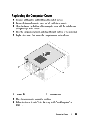
Replacing the Computer Cover 1 Connect all the cables and fold the cables out of the way. 2 Ensure that no tools or extra parts are left inside the computer. 3 Align the tabs at the bottom of the computer cover with the slots located along the edge of the chassis. 4 Press the computer cover down and slide it towards the front of the computer. 5 Replace the screws that secure the computer cover to the chassis. 2 1 1 screws (2) 2 computer cover 6 Place the computer in an upright position. 7 Follow the instructions in "After Working Inside Your Computer" on page 11. Computer Cover 19
Replacing the Computer Cover 1 Connect all the cables and fold the cables out of the way. 2 Ensure that no tools or extra parts are left inside the computer. 3 Align the tabs at the bottom of the computer cover with the slots located along the edge of the chassis. 4 Press the computer cover down and slide it towards the front of the computer. 5 Replace the screws that secure the computer cover to the chassis. 2 1 1 screws (2) 2 computer cover 6 Place the computer in an upright position. 7 Follow the instructions in "After Working Inside Your Computer" on page 11. Computer Cover 19

Owners Manual
Page 26
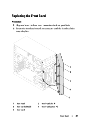
Procedure 1 Place the computer in an upright position. 2 Grasp and release the front bezel tabs sequentially, one at a time by moving them outward from the front panel. 3 Rotate and pull the front bezel away from the front of the computer to release the front bezel clamps from the front panel slots. 1 2 3 4 5 1 front bezel 3 front bezel tabs (4) 5 front panel 2 front panel slots (4) 4 front bezel clamps (4) 4 Set aside the front bezel in a secure location. 26 Front Bezel
Procedure 1 Place the computer in an upright position. 2 Grasp and release the front bezel tabs sequentially, one at a time by moving them outward from the front panel. 3 Rotate and pull the front bezel away from the front of the computer to release the front bezel clamps from the front panel slots. 1 2 3 4 5 1 front bezel 3 front bezel tabs (4) 5 front panel 2 front panel slots (4) 4 front bezel clamps (4) 4 Set aside the front bezel in a secure location. 26 Front Bezel
Owners Manual
Page 27
Replacing the Front Bezel Procedure 1 Align and insert the front bezel clamps into the front panel slots. 2 Rotate the front bezel towards the computer until the front bezel tabs snap into place. 1 2 3 4 1 front bezel 3 front panel slots (4) 5 front panel 5 2 front bezel tabs (4) 4 front bezel clamps (4) Front Bezel 27
Replacing the Front Bezel Procedure 1 Align and insert the front bezel clamps into the front panel slots. 2 Rotate the front bezel towards the computer until the front bezel tabs snap into place. 1 2 3 4 1 front bezel 3 front panel slots (4) 5 front panel 5 2 front bezel tabs (4) 4 front bezel clamps (4) Front Bezel 27
Owners Manual
Page 34
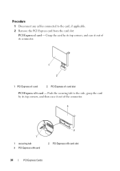
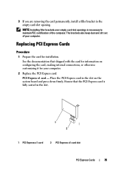
Grasp the card by its connector. 1 2 1 PCI Express x1 card 2 PCI Express x1 card slot PCI Express x16 card - Procedure 1 Disconnect any cables connected to the side, grasp the card by its top corners, and ease it out of its top corners, and then ease it out of the connector. 3 1 1 securing tab 3 PCI Express x16 card 2 2 PCI Express x16 card slot 34 PCI Express Cards Push the securing tab to the card, if applicable. 2 Remove the PCI Express card from the card slot: PCI Express x1 card -
Grasp the card by its connector. 1 2 1 PCI Express x1 card 2 PCI Express x1 card slot PCI Express x16 card - Procedure 1 Disconnect any cables connected to the side, grasp the card by its top corners, and ease it out of its top corners, and then ease it out of the connector. 3 1 1 securing tab 3 PCI Express x16 card 2 2 PCI Express x16 card slot 34 PCI Express Cards Push the securing tab to the card, if applicable. 2 Remove the PCI Express card from the card slot: PCI Express x1 card -
Owners Manual
Page 35
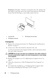
... card: PCI Express x1 card - The brackets also keep dust and dirt out of the computer. Place the PCI Express card in the slot on configuring the card, making internal connections, or otherwise customizing it for installation. 3 If you are removing the card permanently, install a ...filler bracket in the slot. 1 2 1 PCI Express x1 card 2 PCI Express x1 card slot PCI Express Cards 35 NOTE: Installing filler brackets over empty card-slot openings is fully seated in the empty card...
... card: PCI Express x1 card - The brackets also keep dust and dirt out of the computer. Place the PCI Express card in the slot on configuring the card, making internal connections, or otherwise customizing it for installation. 3 If you are removing the card permanently, install a ...filler bracket in the slot. 1 2 1 PCI Express x1 card 2 PCI Express x1 card slot PCI Express Cards 35 NOTE: Installing filler brackets over empty card-slot openings is fully seated in the empty card...
Owners Manual
Page 36
... closing properly or cause damage to the side and place the PCI Express card in the slot on page 19. 4 Follow the instructions in the slot. 3 2 1 1 securing tab 3 PCI Express x16 card 2 PCI Express x16 card slot Postrequisites 1 Replace the card retention bracket. See "Replacing the Computer Cover" on the system board and...
... closing properly or cause damage to the side and place the PCI Express card in the slot on page 19. 4 Follow the instructions in the slot. 3 2 1 1 securing tab 3 PCI Express x16 card 2 PCI Express x16 card slot Postrequisites 1 Replace the card retention bracket. See "Replacing the Computer Cover" on the system board and...

Owners Manual
Page 39
Your computer supports one half Mini-Card slot for Mini-Cards from sources other than Dell. If you ordered a wireless Mini-Card with your computer. NOTE: Dell does not guarantee compatibility or provide support for Wireless Local Area Network (WLAN). Mini-Card 39 CAUTION: When the..., store it in "Before You Begin" on page 9. For additional safety best practices information, see the Regulatory Compliance Homepage at dell.com/regulatory_compliance. Mini-Card WARNING: Before working inside your computer, read the safety information that shipped with your computer and follow the...
Your computer supports one half Mini-Card slot for Mini-Cards from sources other than Dell. If you ordered a wireless Mini-Card with your computer. NOTE: Dell does not guarantee compatibility or provide support for Wireless Local Area Network (WLAN). Mini-Card 39 CAUTION: When the..., store it in "Before You Begin" on page 9. For additional safety best practices information, see the Regulatory Compliance Homepage at dell.com/regulatory_compliance. Mini-Card WARNING: Before working inside your computer, read the safety information that shipped with your computer and follow the...
Owners Manual
Page 41
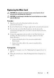
..." on the system board and replace the screw that there are no cables under the Mini-Card. Use of the Mini-Card down into the slot on page 11. Replacing the Mini-Card CAUTION: The connectors are keyed to the connector marked with a white triangle.
..." on the system board and replace the screw that there are no cables under the Mini-Card. Use of the Mini-Card down into the slot on page 11. Replacing the Mini-Card CAUTION: The connectors are keyed to the connector marked with a white triangle.
Owners Manual
Page 59
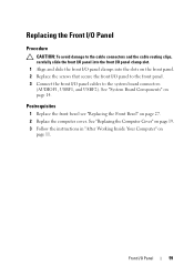
... I/O panel cables to the cable connectors and the cable routing clips, carefully slide the front I/O panel into the front I/O panel clamp slot. 1 Align and slide the front I/O panel clamps into the slots on page 14. Replacing the Front I/O Panel Procedure CAUTION: To avoid damage to the system board connectors (AUDIOF1, USBF1, and...
... I/O panel cables to the cable connectors and the cable routing clips, carefully slide the front I/O panel into the front I/O panel clamp slot. 1 Align and slide the front I/O panel clamps into the slots on page 14. Replacing the Front I/O Panel Procedure CAUTION: To avoid damage to the system board connectors (AUDIOF1, USBF1, and...
Owners Manual
Page 63
See "Replacing the Front Bezel" on page 11. Power Button Module 63 See "Replacing the Computer Cover" on page 19. 3 Follow the instructions in "After Working Inside Your Computer" on page 27. 2 Replace the computer cover. See "System Board Components" on the front panel. 2 Connect the power button module cable to the system board connector (LEDH2). Replacing the Power Button Module Procedure 1 Align and push the power button module tabs into the slots on page 14. Postrequisites 1 Replace the front bezel.
See "Replacing the Front Bezel" on page 11. Power Button Module 63 See "Replacing the Computer Cover" on page 19. 3 Follow the instructions in "After Working Inside Your Computer" on page 27. 2 Replace the computer cover. See "System Board Components" on the front panel. 2 Connect the power button module cable to the system board connector (LEDH2). Replacing the Power Button Module Procedure 1 Align and push the power button module tabs into the slots on page 14. Postrequisites 1 Replace the front bezel.

Owners Manual
Page 85
...page 40. 3 Remove the any PCI-Express cards, if applicable. System Board 85 Record which memory module is removed from each DIMM slot so that shipped with your computer, read the safety information that the memory modules can be installed in "Before You Begin" on page... 9. For additional safety best practices information, see the Regulatory Compliance Homepage at dell.com/regulatory_compliance. Removing the System Board Prerequisites 1 Remove the computer cover. System Board WARNING: Before working inside your computer and follow ...
...page 40. 3 Remove the any PCI-Express cards, if applicable. System Board 85 Record which memory module is removed from each DIMM slot so that shipped with your computer, read the safety information that the memory modules can be installed in "Before You Begin" on page... 9. For additional safety best practices information, see the Regulatory Compliance Homepage at dell.com/regulatory_compliance. Removing the System Board Prerequisites 1 Remove the computer cover. System Board WARNING: Before working inside your computer and follow ...


