
Terminator C3V User Manual
Page 14
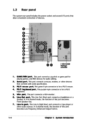
... a PS/2 mouse. 4 . L i n e I p o r t . In 6-channel mode, the function of this port becomes Low Frequency Enhanced Output/Center. 1-4 Chapter 1: System introduction This green 6-pin connector is for audio editing. 2 . This port connects a VGA monitor. 6 . L i n e O u t p o r t . G A M E / M I D I n p o r t . P S / 2 m o u s e p o r t . This Line In (light blue) port connects a tape player or other devices that allow convenient ...several I/O ports that conform with serial specification. 3 . V G A p o r t . This port connects a mouse, modem, or other audio sources.
... a PS/2 mouse. 4 . L i n e I p o r t . In 6-channel mode, the function of this port becomes Low Frequency Enhanced Output/Center. 1-4 Chapter 1: System introduction This green 6-pin connector is for audio editing. 2 . This port connects a VGA monitor. 6 . L i n e O u t p o r t . G A M E / M I D I n p o r t . P S / 2 m o u s e p o r t . This Line In (light blue) port connects a tape player or other devices that allow convenient ...several I/O ports that conform with serial specification. 3 . V G A p o r t . This port connects a mouse, modem, or other audio sources.
Terminator C3V User Manual
Page 15
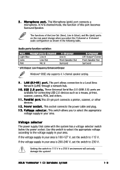
...p o r t s . P a r a l l e l p o r t .This 25-pin port connects a printer, scanner, or other devices. 1 2 . M i c r o p h o n e p o r t . Audio ports function variation Port Headphone/2-Channel Light Blue Line In Lime Line Out Pink Mic In 4-Channel Line In Front Speaker Out Surround * LFE Output... Line Out (lime), Line In (blue), and Mic (pink) ports on the rear panel change when you to a Local Area Network (LAN) through a network hub. 1 0 . ASUS Terminator 1 C3 barebone system 1-5 L A N ( R J - 4 5 ) p o r t . P o w e r s o c k e t . Use this port becomes Surround ...
...p o r t s . P a r a l l e l p o r t .This 25-pin port connects a printer, scanner, or other devices. 1 2 . M i c r o p h o n e p o r t . Audio ports function variation Port Headphone/2-Channel Light Blue Line In Lime Line Out Pink Mic In 4-Channel Line In Front Speaker Out Surround * LFE Output... Line Out (lime), Line In (blue), and Mic (pink) ports on the rear panel change when you to a Local Area Network (LAN) through a network hub. 1 0 . ASUS Terminator 1 C3 barebone system 1-5 L A N ( R J - 4 5 ) p o r t . P o w e r s o c k e t . Use this port becomes Surround ...
Terminator C3V User Manual
Page 16
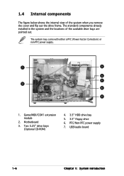
The standard components already installed in the system and the locations of the system when you remove the cover and flip out the drive frame. The system may come with either a PFC (Power Factor Correction) or non-PFC power supply. 1 3 4 5 2 6 7 1. 1.4 Internal components The figure below shows the internal view of the available drive bays are pointed out. Motherboard 3. USB/audio board 1-6 Chapter 1: System introduction PFC/Non-PFC power supply 7. Game/MIDI/COM1 extension module 2. Two 5.25" drive bays (Optional CD-ROM) 4. 3.5" HDD drive bay 5. 3.5" floppy drive 6.
The standard components already installed in the system and the locations of the system when you remove the cover and flip out the drive frame. The system may come with either a PFC (Power Factor Correction) or non-PFC power supply. 1 3 4 5 2 6 7 1. 1.4 Internal components The figure below shows the internal view of the available drive bays are pointed out. Motherboard 3. USB/audio board 1-6 Chapter 1: System introduction PFC/Non-PFC power supply 7. Game/MIDI/COM1 extension module 2. Two 5.25" drive bays (Optional CD-ROM) 4. 3.5" HDD drive bay 5. 3.5" floppy drive 6.

Terminator C3V User Manual
Page 26
... 5 11* 6 12* 7 13 8 14* 9 15* 10 Standard Function System Timer Keyboard Controller Programmable Interrupt USB Universal Host Controller Communications Port (COM1) Onboard Audio Standard Floppy Disk Controller Printer Port (LPT1) System CMOS/Real Time Clock ACPI Mode when used IRQ Holder for PCI Steering Onboard LAN PS/2 Compatible... 2.6.5 IRQ assignments for this motherboard PCI slot USB 1.1 UHCI 1 USB 1.1 UHCI 1 USB 1.1 UHCI 1 USB 2.0 EHCI Onboard Audio Onboard LAN ABCDE F G H used shared used shared used shared - - - - - shared - - - 2-10 Chapter 2: Basic Installation
... 5 11* 6 12* 7 13 8 14* 9 15* 10 Standard Function System Timer Keyboard Controller Programmable Interrupt USB Universal Host Controller Communications Port (COM1) Onboard Audio Standard Floppy Disk Controller Printer Port (LPT1) System CMOS/Real Time Clock ACPI Mode when used IRQ Holder for PCI Steering Onboard LAN PS/2 Compatible... 2.6.5 IRQ assignments for this motherboard PCI slot USB 1.1 UHCI 1 USB 1.1 UHCI 1 USB 1.1 UHCI 1 USB 2.0 EHCI Onboard Audio Onboard LAN ABCDE F G H used shared used shared used shared - - - - - shared - - - 2-10 Chapter 2: Basic Installation
Terminator C3V User Manual
Page 28
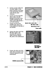
Red stripe to the secondary IDE connector (black connector labeled SEC_IDE) on the motherboard. 9. Connect the other end of the audio cable to the power connector at the back of the IDE ribbon cable to Pin 1 Power cable 8. Connect the other end of the CD-ROM. ... the back of the CD-ROM, matching the red stripe on the cable with the white connector. 6. 5. Connect one end of the Optical drive audio cable CD-ROM audio cable to the IDE interface at the back of the optical drive. Use the cable with Pin 1 on the motherboard. Connect a power cable...
Red stripe to the secondary IDE connector (black connector labeled SEC_IDE) on the motherboard. 9. Connect the other end of the audio cable to the power connector at the back of the IDE ribbon cable to Pin 1 Power cable 8. Connect the other end of the CD-ROM. ... the back of the CD-ROM, matching the red stripe on the cable with the white connector. 6. 5. Connect one end of the Optical drive audio cable CD-ROM audio cable to the IDE interface at the back of the optical drive. Use the cable with Pin 1 on the motherboard. Connect a power cable...
Terminator C3V User Manual
Page 39
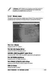
Double-click the ASSETUP.EXE to activate the devices. ASUS Terminator 1 C3 barebone system 3-3 USB 2.0 Driver Installs the USB 2.0 driver. VIA 4 in 1 Drivers Installs the VIA 4-in your computer, browse the contents of the support CD to ... if the system detects installed devices. VIA CLE 266 Display Driver Installs the VIA CLE 266 display driver. AD1980_1888 SoundMAX® Audio Driver Installs the ADI® 1980/1888 SoundMAX® audio driver and application. VIA VT6420 (VT8237) SATA driver Installs the VIA VT6420 (VT8237) Serial ATA driver. VIA 10/100Mb LAN...
Double-click the ASSETUP.EXE to activate the devices. ASUS Terminator 1 C3 barebone system 3-3 USB 2.0 Driver Installs the USB 2.0 driver. VIA 4 in 1 Drivers Installs the VIA 4-in your computer, browse the contents of the support CD to ... if the system detects installed devices. VIA CLE 266 Display Driver Installs the VIA CLE 266 display driver. AD1980_1888 SoundMAX® Audio Driver Installs the ADI® 1980/1888 SoundMAX® audio driver and application. VIA VT6420 (VT8237) SATA driver Installs the VIA VT6420 (VT8237) Serial ATA driver. VIA 10/100Mb LAN...

Terminator C3V User Manual
Page 56
... incorrect insertion when using ribbon cables with pin 5 plug). ® C3V FLOPPY NOTE: Orient the red markings on the floppy ribbon cable to receive stereo audio input from sound sources such as an optical drive, TV tuner, or MPEG card. ® C3V CD AUX C3V Internal...
... incorrect insertion when using ribbon cables with pin 5 plug). ® C3V FLOPPY NOTE: Orient the red markings on the floppy ribbon cable to receive stereo audio input from sound sources such as an optical drive, TV tuner, or MPEG card. ® C3V CD AUX C3V Internal...
Terminator C3V User Manual
Page 57
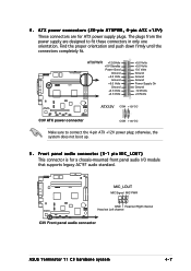
... ATX power connectors (20-pin ATXPWR, 4-pin ATX +12V) These connectors are designed to connect the 4-pin ATX +12V power plug; Front panel audio connector (5-1 pin MIC_LOUT) This connector is for ATX power supply plugs. otherwise, the system does not boot up. 5 . The plugs from the .... ® C3V MIC_LOUT MIC Signal MIC PWR 1 GND Head set Right channel Head set Left channel C3V Front panel audio connector ASUS Terminator T1 C3 barebone system 4-7 Find the proper orientation and push down firmly until the connectors completely fit. ® C3V ATXPWR +12.0Volts +5V Standby...
... ATX power connectors (20-pin ATXPWR, 4-pin ATX +12V) These connectors are designed to connect the 4-pin ATX +12V power plug; Front panel audio connector (5-1 pin MIC_LOUT) This connector is for ATX power supply plugs. otherwise, the system does not boot up. 5 . The plugs from the .... ® C3V MIC_LOUT MIC Signal MIC PWR 1 GND Head set Right channel Head set Left channel C3V Front panel audio connector ASUS Terminator T1 C3 barebone system 4-7 Find the proper orientation and push down firmly until the connectors completely fit. ® C3V ATXPWR +12.0Volts +5V Standby...

Terminator C3V User Manual
Page 59
... disk drives. Connect the S/PDIF module cable to this connector, then install the module to a slot opening at the back of the system chassis. Digital audio connector (4-1 pin SPDIF_OUT) This connector is purchased separately. ® C3V +5V SPDIFOUT GND C3V Digital audio connector SPDIF_OUT ASUS Terminator T1 C3 barebone system 4-9 8 .
... disk drives. Connect the S/PDIF module cable to this connector, then install the module to a slot opening at the back of the system chassis. Digital audio connector (4-1 pin SPDIF_OUT) This connector is purchased separately. ® C3V +5V SPDIFOUT GND C3V Digital audio connector SPDIF_OUT ASUS Terminator T1 C3 barebone system 4-9 8 .
Terminator C3V User Manual
Page 79
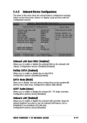
... on the onboard LAN chipset. Keep the default enabled if you to use the onboard LAN feature. Configuration options: [Auto] [Disabled] ASUS Terminator 1 C3 barebone system 5-17 Set to [RAID], this menu show the onboard device configuration settings. Configuration options: [Disabled] [Enabled] SATA Mode ...] Onboard LAN [Enabled] Allows you installed a PCI LAN card. Onboard Device Configuration Onboard LAN Boot ROM OnChip SATA SATA Mode AC97 Audio Onboard LAN Serial Port1 Address Parallel Port Address Parallel Port Mode X EPP Mode Select X ECP Mode Use DMA Game Port Address Midi ...
... on the onboard LAN chipset. Keep the default enabled if you to use the onboard LAN feature. Configuration options: [Auto] [Disabled] ASUS Terminator 1 C3 barebone system 5-17 Set to [RAID], this menu show the onboard device configuration settings. Configuration options: [Disabled] [Enabled] SATA Mode ...] Onboard LAN [Enabled] Allows you installed a PCI LAN card. Onboard Device Configuration Onboard LAN Boot ROM OnChip SATA SATA Mode AC97 Audio Onboard LAN Serial Port1 Address Parallel Port Address Parallel Port Mode X EPP Mode Select X ECP Mode Use DMA Game Port Address Midi ...