Asus Terminator P-III Support and Manuals
Get Help and Manuals for this Asus item
View All Support Options Below
Free Asus Terminator P-III manuals!
Problems with Asus Terminator P-III?
Ask a Question
Free Asus Terminator P-III manuals!
Problems with Asus Terminator P-III?
Ask a Question
Popular Asus Terminator P-III Manual Pages
E787 MANUAL TERMINATOR English - Page 2

... or service will not be extended if: (1) the product is repaired, modified or altered, unless such repair, modification of alteration is defaced or missing. SPECIFICATIONS AND INFORMATION CONTAINED IN THIS MANUAL ARE FURNISHED FOR INFORMATIONAL USE ONLY, AND ARE SUBJECT TO CHANGE AT ANY TIME WITHOUT NOTICE, AND SHOULD NOT BE CONSTRUED AS A COMMITMENT BY ASUS. ASUS...
E787 MANUAL TERMINATOR English - Page 5
...15 2.3 Install a CPU 16 2.4 Install System Memory 18 2.5 Install a Hard Disk Drive 19 2.6 Install a CD-ROM Drive 21 2.7 Install a Modem Riser Card 23 2.8 Install a PCI Expansion Card 24 2.9 Re-connect Cables 25 2.10 Replace the Cover 26 2.11 Connect External Devices 28
Chapter 3: Motherboard Information 29
3.1 Motherboard Layout 30 3.2 USB/Audio Board Layout 31 3.3 Jumper Settings 32...
E787 MANUAL TERMINATOR English - Page 8

...-step instructions.
4. It also includes information on the USB/audio board located on the contents of this document that comes with hardware knowledge of the ASUS Terminator barebone system. Checklist
Audience
This installation guide is intended for experienced users and integrators with the ASUS Terminator Barebone System.This chapter includes the motherboard layout, jumper settings, and...
E787 MANUAL TERMINATOR English - Page 10

...
Push the dotted area of the ASUS CUSC motherboard, a power supply, and a floppy disk drive in some models. 1.1 Front Panel Features
The ASUS Terminator barebone system is a door that covers...part of the front panel is composed of the door to open it and show the front panel features. NOTE The CD-ROM drive and modem card are optional items and may not come installed in the ASUS...
E787 MANUAL TERMINATOR English - Page 11

... beside the power socket. If the voltage supply in your area.
ASUS Terminator Barebone System
11 Use this switch to select the appropriate voltage according to 115V in your area is 200-240V, set the switch to 230V.
115V/230V Voltage Selector
CAUTION! Setting the switch to the voltage supply in a 230V environment will...
E787 MANUAL TERMINATOR English - Page 16
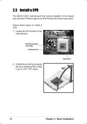
... the lever sideways then lifting it up to install a CPU. 1. CPU Fan Connector (CPU_FAN)
CPU Socket 370
2. Socket Pin 1
16
Chapter 2: Basic Installation 2.3 Install a CPU
The ASUS CUSC motherboard that comes installed in the chassis has a Socket 370 that supports an Intel Pentium III/Celeron processor. Locate the CPU socket on the
motherboard.
Follow these steps to a 90°-100°...
E787 MANUAL TERMINATOR English - Page 17

... CPU. Refer to
the picture in place indicating that the socket is parallel to prevent bending the pins and damaging the CPU.
If the CPU does not fit completely, check its notched or marked corner matches the Socket Pin 1, while making sure that its orientation or check for bent pins. ASUS Terminator Barebone System
17
2.3 Install a CPU...
E787 MANUAL TERMINATOR English - Page 21

... bay.
5.25-inch Drive Bay CD-ROM Screws
ASUS Terminator Barebone System
21 Refer to install a CD-ROM drive. 1. 2.6 Install a CD-ROM Drive
A CD-ROM drive is an optional item in this section if you acquired a model without a CD-ROM. Follow these steps to the instructions in the Terminator barebone system. Carefully push the CD-ROM drive...
E787 MANUAL TERMINATOR English - Page 23

... to the slot
opening on the right shows a modem riser card that supports a modem riser card.
Follow these steps to a Telephone Set
Modem Riser Card Installed on the AMR slot. Bracket Screw
5. 2.7 Install a Modem Riser Card
The motherboard includes an AMR slot that you acquired a model without a modem riser card. Connect to a Telephone Line
Connect to...
E787 MANUAL TERMINATOR English - Page 25

...cables before you were installing components.
IDELED Lead
Pin 1 FLOUT Lead (for Line Out Cable) MIC2 Lead (for Microphone Cable)
ASUS Terminator Barebone System
25 Connect the power switch and power LED cables to the USB1 connector on the motherboard. Connect the USB2P ...an ATX power supply. 2.9 Re-connect Cables
You may have disconnected some cables when you replace the chassis cover.
E787 MANUAL TERMINATOR English - Page 27

2.10 Replace the Cover
5. The locking tab snaps into the hole on the rear panel. Locking Tab
Locking Tab Hole
IMPORTANT ... the edges of the chassis. Rail Tabs
6.
Lock the cover with the captive thumbscrew on the chassis indicating that it fits.
ASUS Terminator Barebone System
27 Push the cover towards the rear until it is in place. Fit the rail tabs on the sides and bottom...
E787 MANUAL TERMINATOR English - Page 29

... on the front panel. M/B Information
ASUS Terminator Barebone System
29 In cases when changing motherboard settings require corresponding BIOS settings adjustments, enter BIOS Setup by pressing the Delete key during boot up (Power-On Self Test). Chapter 3
This chapter gives information about the CUSC motherboard that comes with the ASUS Terminator Barebone System.This chapter includes the...
E787 MANUAL TERMINATOR English - Page 30

.../72-bit, 168-pin module)
®
Line Out
Socket 370
Line In
Mic
In
CPU_FAN
RJ-45 CH_FAN
LANLED
ASUS Mozart
USB
T: Port0 B: Port1
USBPWR1 CD FLOUT
AUX MIC2
PCI Slot 1
Audio Codec
PDN WOR
PCI Slot 2...CMOS Power
1
1
USB1 USBPWR
CLRTC IR
PANEL IDELED
30
Chapter 3: Motherboard Information 3.1 Motherboard Layout
Refer to the layout below to locate specific motherboard components.
E787 MANUAL TERMINATOR English - Page 31

...;
LOUT
LO2 MIC
MIC2
Connect to USB1 Connector on the Motherboard
Connect to FLOUT Lead on the Motherboard
ASUS Terminator Barebone System
31
3.2 USB/Audio Board Layout
The USB/audio board is located on the front panel to MIC2 Lead on the Motherboard Connect to support externally accessible connectors including two USB, headphone, and microphone connectors...
E787 MANUAL TERMINATOR English - Page 32

...) Frequency Selection
CPU
1
1
1
(Default)
66.6MHz 100.0MHz 133.3MHz
SDRAM 100.0MHz 133.3MHz 133.3MHz
PCI
33.3MHz 33.3MHz 33.3MHz
2. 3.3 Jumper Settings
The following jumper settings are for your reference in slow refresh; CUSC
®
CUSC USB Device Wake Up
USBPWR USBPWR1
12 +5VSB
23 +5V
32
Chapter 3: Motherboard Information
Asus Terminator P-III Reviews
We have not received any reviews for Asus yet.