
Terminator C3V User Manual
Page 3
...2-4 2.5 Installing system memory 2-6 2.5.1 Memory configurations 2-6 2.5.2 DIMM installation 2-7 2.6 Installing an expansion card 2-8 2.6.1 Expansion slot 2-8 2.6.2 Expansion card installation 2-9 2.6.3 Configuring an expansion card 2-9 2.6.4 Standard interrupt assignments 2-10 2.6.5 IRQ assignments for this motherboard 2-10 2.7 Installing an optical drive 2-11 2.8 Installing a hard disk drive 2-13 2.9 Re-connecting cables 2-15 2.9.1 LED cables 2-15 2.9.2 UAEX module 2-16 2.10 Replacing the cover 2-17 2.11 Connecting external devices 2-19 2.12 Power supply specifications 2-20...
...2-4 2.5 Installing system memory 2-6 2.5.1 Memory configurations 2-6 2.5.2 DIMM installation 2-7 2.6 Installing an expansion card 2-8 2.6.1 Expansion slot 2-8 2.6.2 Expansion card installation 2-9 2.6.3 Configuring an expansion card 2-9 2.6.4 Standard interrupt assignments 2-10 2.6.5 IRQ assignments for this motherboard 2-10 2.7 Installing an optical drive 2-11 2.8 Installing a hard disk drive 2-13 2.9 Re-connecting cables 2-15 2.9.1 LED cables 2-15 2.9.2 UAEX module 2-16 2.10 Replacing the cover 2-17 2.11 Connecting external devices 2-19 2.12 Power supply specifications 2-20...
Terminator C3V User Manual
Page 6
... for a Class B digital device, pursuant to Part 15 of the monitor to the graphics card is subject to the following measures: • Reorient or relocate the receiving antenna. • Increase the separation between the equipment and receiver. • Connect the equipment to assure compliance with Canadian ICES-003. The use of shielded cables for help. Operation is required to...
... for a Class B digital device, pursuant to Part 15 of the monitor to the graphics card is subject to the following measures: • Reorient or relocate the receiving antenna. • Increase the separation between the equipment and receiver. • Connect the equipment to assure compliance with Canadian ICES-003. The use of shielded cables for help. Operation is required to...

Terminator C3V User Manual
Page 8
... about the ASUS Terminator 1 barebone system. The chapter lists the system features including introduction on how to change system settings through the BIOS Setup menus and describes the BIOS parameters. viii How this guide Audience This guide provides general information and installation instructions about the motherboard that comes with hardware knowledge of the ASUS Terminator 1. This chapter includes the motherboard layout, jumper settings, and connector locations. 5. This guide is organized This guide contains the...
... about the ASUS Terminator 1 barebone system. The chapter lists the system features including introduction on how to change system settings through the BIOS Setup menus and describes the BIOS parameters. viii How this guide Audience This guide provides general information and installation instructions about the motherboard that comes with hardware knowledge of the ASUS Terminator 1. This chapter includes the motherboard layout, jumper settings, and connector locations. 5. This guide is organized This guide contains the...
Terminator C3V User Manual
Page 10
Power cable and plug 3. x ASUS Terminator 1 barebone system with: • ASUS C3V motherboard with onboard VIA C3 CPU • Floppy disk drive • Optical drive (optional)* 2. User guide * CD-ROM/CD-RW/DVD-ROM/DVD-RW If any of the items is damaged or missing, contact your ASUS Terminator 1 package for the following items: 1 . Support CD 4. System package contents Check your retailer immediately.
Power cable and plug 3. x ASUS Terminator 1 barebone system with: • ASUS C3V motherboard with onboard VIA C3 CPU • Floppy disk drive • Optical drive (optional)* 2. User guide * CD-ROM/CD-RW/DVD-ROM/DVD-RW If any of the items is damaged or missing, contact your ASUS Terminator 1 package for the following items: 1 . Support CD 4. System package contents Check your retailer immediately.
Terminator C3V User Manual
Page 14
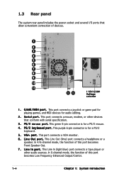
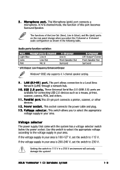
... port connects a VGA monitor. 6 . This Line Out (lime) port connects a headphone or a speaker. This Line In (light blue) port connects a tape player or other devices that allow convenient connection of this port becomes Low Frequency Enhanced Output/Center. 1-4 Chapter 1: System introduction S e r i a l p o r t . P S / 2 m o u s e p o r t . L i n e O u t p o r t . In 6-channel mode, the function of this port becomes Front Speaker Out. 7 . V G A p o r t . L i n e I /O ports that conform with serial specification. 3 . 1.3 Rear panel The system rear panel includes the power...
... port connects a VGA monitor. 6 . This Line Out (lime) port connects a headphone or a speaker. This Line In (light blue) port connects a tape player or other devices that allow convenient connection of this port becomes Low Frequency Enhanced Output/Center. 1-4 Chapter 1: System introduction S e r i a l p o r t . P S / 2 m o u s e p o r t . L i n e O u t p o r t . In 6-channel mode, the function of this port becomes Front Speaker Out. 7 . V G A p o r t . L i n e I /O ports that conform with serial specification. 3 . 1.3 Rear panel The system rear panel includes the power...
Terminator C3V User Manual
Page 15
... LFE Output*/Center Front Speaker Out Surround Windows® 98SE only supports 4.1-channel speaker setting. 9 . U S B 2 . 0 p o r t s . P a r a l l e l p o r t .This 25-pin port connects a printer, scanner, or other devices. 1 2 . In 4/6-channel mode, the function of the Line Out (lime), Line In (blue), and Mic (pink) ports on the rear panel change when you to a Local Area Network (LAN) through a network hub. 1 0 . This switch allows you select the 4-channel or 6-channel audio configuration as a mouse, printer, scanner...
... LFE Output*/Center Front Speaker Out Surround Windows® 98SE only supports 4.1-channel speaker setting. 9 . U S B 2 . 0 p o r t s . P a r a l l e l p o r t .This 25-pin port connects a printer, scanner, or other devices. 1 2 . In 4/6-channel mode, the function of the Line Out (lime), Line In (blue), and Mic (pink) ports on the rear panel change when you to a Local Area Network (LAN) through a network hub. 1 0 . This switch allows you select the 4-channel or 6-channel audio configuration as a mouse, printer, scanner...

Terminator C3V User Manual
Page 18
... power supply case, before installing any component, place it on a grounded antistatic pad or in the bag that came with an onboard standby power LED. 2.1 Preparation Before you proceed, make sure that the standby power LED is ON, in sleep mode or in soft-off mode, and not powered OFF. Expansion card(s) 3. This LED lights up to install in the system. Unplug the power cable from the power outlet and make...
... power supply case, before installing any component, place it on a grounded antistatic pad or in the bag that came with an onboard standby power LED. 2.1 Preparation Before you proceed, make sure that the standby power LED is ON, in sleep mode or in soft-off mode, and not powered OFF. Expansion card(s) 3. This LED lights up to install in the system. Unplug the power cable from the power outlet and make...
Terminator C3V User Manual
Page 25
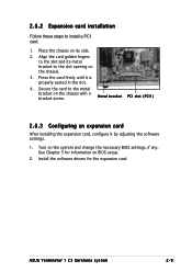
Install the software drivers for information on the system and change the necessary BIOS settings, if any. See Chapter 5 for the expansion card. Align the card golden fingers to the slot and its side. 2. Press the card firmly until it by adjusting the software settings. 1. ASUS Terminator 1 C3 barebone system 2-9 Secure the card to the slot opening on the chassis with a bracket screw. Metal bracket PCI slot (PCI1) 2.6.3 Configuring an expansion card After...
Install the software drivers for information on the system and change the necessary BIOS settings, if any. See Chapter 5 for the expansion card. Align the card golden fingers to the slot and its side. 2. Press the card firmly until it by adjusting the software settings. 1. ASUS Terminator 1 C3 barebone system 2-9 Secure the card to the slot opening on the chassis with a bracket screw. Metal bracket PCI slot (PCI1) 2.6.3 Configuring an expansion card After...
Terminator C3V User Manual
Page 27
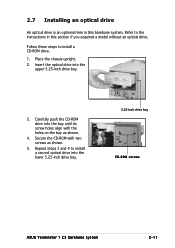
... optical drive An optical drive is an optional item in this barebone system. Place the chassis upright. 2. Follow these steps to install a second optical drive into the lower 5.25-inch drive bay. 5.25-inch drive bay CD-ROM screws ASUS Terminator 1 C3 barebone system 2-11 Carefully push the CD-ROM drive into the upper 5.25-inch drive bay. 3. Refer to the instructions in this section if you acquired a model...
... optical drive An optical drive is an optional item in this barebone system. Place the chassis upright. 2. Follow these steps to install a second optical drive into the lower 5.25-inch drive bay. 5.25-inch drive bay CD-ROM screws ASUS Terminator 1 C3 barebone system 2-11 Carefully push the CD-ROM drive into the upper 5.25-inch drive bay. 3. Refer to the instructions in this section if you acquired a model...
Terminator C3V User Manual
Page 38
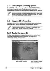
... screen. 3-2 Click an item to install Click an icon to change at any time without notice. The contents of your CD-ROM drive. Because motherboard settings and hardware options vary, use the setup procedures presented in your computer, the Drivers menu automatically appears on your OS documentation for more information Chapter 3: Starting up If Autorun is enabled in this chapter for updates. 3.2.1 Running the support CD To begin using...
... screen. 3-2 Click an item to install Click an icon to change at any time without notice. The contents of your CD-ROM drive. Because motherboard settings and hardware options vary, use the setup procedures presented in your computer, the Drivers menu automatically appears on your OS documentation for more information Chapter 3: Starting up If Autorun is enabled in this chapter for updates. 3.2.1 Running the support CD To begin using...
Terminator C3V User Manual
Page 39
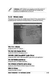
... (VT8237) Serial ATA driver. USB 2.0 Driver Installs the USB 2.0 driver. VIA CLE 266 Display Driver Installs the VIA CLE 266 display driver. Install the necessary drivers to locate the file ASSETUP.EXE from the BIN folder. VIA 4 in 1 Drivers Installs the VIA 4-in your computer, browse the contents of the support CD to activate the devices. AD1980_1888 SoundMAX® Audio Driver Installs the ADI® 1980/1888 SoundMAX® audio driver and application. ASUS Terminator 1 C3 barebone...
... (VT8237) Serial ATA driver. USB 2.0 Driver Installs the USB 2.0 driver. VIA CLE 266 Display Driver Installs the VIA CLE 266 display driver. Install the necessary drivers to locate the file ASSETUP.EXE from the BIN folder. VIA 4 in 1 Drivers Installs the VIA 4-in your computer, browse the contents of the support CD to activate the devices. AD1980_1888 SoundMAX® Audio Driver Installs the ADI® 1980/1888 SoundMAX® audio driver and application. ASUS Terminator 1 C3 barebone...
Terminator C3V User Manual
Page 54
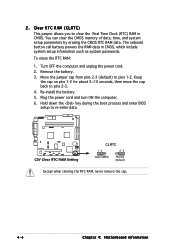
... Clear RTC RAM Setting CLRTC 12 23 Clear CMOS Normal (Default) Except when clearing the RTC RAM, never remove the cap. 4-4 Chapter 4: Motherboard information You can clear the CMOS memory of date, time, and system setup parameters by erasing the CMOS RTC RAM data. The onboard button cell battery powers the RAM data in CMOS. Hold down the key during the boot process and enter BIOS setup to pins 1-2. Turn OFF the computer and unplug the power cord. 2. Remove the battery. 3. Plug...
... Clear RTC RAM Setting CLRTC 12 23 Clear CMOS Normal (Default) Except when clearing the RTC RAM, never remove the cap. 4-4 Chapter 4: Motherboard information You can clear the CMOS memory of date, time, and system setup parameters by erasing the CMOS RTC RAM data. The onboard button cell battery powers the RAM data in CMOS. Hold down the key during the boot process and enter BIOS setup to pins 1-2. Turn OFF the computer and unplug the power cord. 2. Remove the battery. 3. Plug...
Terminator C3V User Manual
Page 55
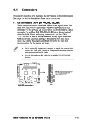
... connector is removed to PIN 1. PIN 1 ASUS Terminator T1 C3 barebone system 4-5 Refer to the hard disk documentation for the jumper settings. • Pin 20 on the motherboard, a black connector for an Ultra DMA 133/100/66 IDE slave device (optical drive/hard disk drive), and a gray connector for Ultra DMA 133/100/66 signal cables. If you install two hard disk drives, you connect the IDE cable. • Use the 80-conductor IDE cable for the description of rear panel connectors. 1 . IDE connectors (40-1 pin...
... connector is removed to PIN 1. PIN 1 ASUS Terminator T1 C3 barebone system 4-5 Refer to the hard disk documentation for the jumper settings. • Pin 20 on the motherboard, a black connector for an Ultra DMA 133/100/66 IDE slave device (optical drive/hard disk drive), and a gray connector for Ultra DMA 133/100/66 signal cables. If you install two hard disk drives, you connect the IDE cable. • Use the 80-conductor IDE cable for the description of rear panel connectors. 1 . IDE connectors (40-1 pin...
Terminator C3V User Manual
Page 69
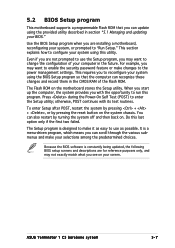
... through the various submenus and make it as easy to make your selections among the predetermined choices. otherwise, POST continues with the opportunity to the power management settings. This section explains how to enter the Setup utility; ASUS Terminator 1 C3 barebone system 5-7 For example, you can update using this last option only if the first two failed. 5.2 BIOS Setup program This motherboard supports a programmable Flash ROM that the computer can...
... through the various submenus and make it as easy to make your selections among the predetermined choices. otherwise, POST continues with the opportunity to the power management settings. This section explains how to enter the Setup utility; ASUS Terminator 1 C3 barebone system 5-7 For example, you can update using this last option only if the first two failed. 5.2 BIOS Setup program This motherboard supports a programmable Flash ROM that the computer can...
Terminator C3V User Manual
Page 76
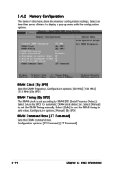
... the memory configuration settings. Configuration options: [66 MHz] [100 MHz] [133 MHz] [By SPD] DRAM Timing [By SPD] The DRAM clock is set according to set the DRAM timing to display a pop-up menu with the configuration options. Configuration options: [Manual] [By SPD] DRAM Command Rate [2T Command] Sets the DRAM command rate . Select [Manual] to DRAM SPD (Serial Presence Detect). Configuration options: [2T Command] [1T Command] 5-14 Chapter 5: BIOS...
... the memory configuration settings. Configuration options: [66 MHz] [100 MHz] [133 MHz] [By SPD] DRAM Timing [By SPD] The DRAM clock is set according to set the DRAM timing to display a pop-up menu with the configuration options. Configuration options: [Manual] [By SPD] DRAM Command Rate [2T Command] Sets the DRAM command rate . Select [Manual] to DRAM SPD (Serial Presence Detect). Configuration options: [2T Command] [1T Command] 5-14 Chapter 5: BIOS...
Terminator C3V User Manual
Page 78
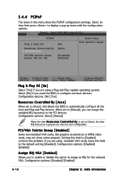
... operating system. PCI/VGA Palette Snoop [Disabled] Some non-standard VGA cards, like graphics accelerators or MPEG video cards, may not show the PCIPnP configuration settings. Setting this allows the BIOS to assign an IRQ for VGA [No] [Auto] [Disabled] [Enabled] Select Menu Item Specific Help Plug & Play OS [No] Select [Yes] if you need the BIOS to [Enabled] corrects this field to [Auto], the item IRQ Resources is set to the default setting [Disabled]. When set...
... operating system. PCI/VGA Palette Snoop [Disabled] Some non-standard VGA cards, like graphics accelerators or MPEG video cards, may not show the PCIPnP configuration settings. Setting this allows the BIOS to assign an IRQ for VGA [No] [Auto] [Disabled] [Enabled] Select Menu Item Specific Help Plug & Play OS [No] Select [Yes] if you need the BIOS to [Enabled] corrects this field to [Auto], the item IRQ Resources is set to the default setting [Disabled]. When set...
Terminator C3V User Manual
Page 79
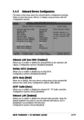
... boot ROM of the installed IDE devices into a disk array. Configuration options: [IDE] [RAID] AC97 Audio [Auto] Allows you installed a PCI LAN card. Set to [Disabled] if you to enable or disable the onboard LAN controller. Configuration options: [Auto] [Disabled] ASUS Terminator 1 C3 barebone system 5-17 Onboard Device Configuration Onboard LAN Boot ROM OnChip SATA SATA Mode AC97 Audio Onboard LAN Serial Port1 Address Parallel Port Address Parallel Port Mode X EPP Mode Select X ECP Mode Use DMA Game Port Address Midi Port Address x Midi Port IRQ [Disabled] [Enabled] [RAID...
... boot ROM of the installed IDE devices into a disk array. Configuration options: [IDE] [RAID] AC97 Audio [Auto] Allows you installed a PCI LAN card. Set to [Disabled] if you to enable or disable the onboard LAN controller. Configuration options: [Auto] [Disabled] ASUS Terminator 1 C3 barebone system 5-17 Onboard Device Configuration Onboard LAN Boot ROM OnChip SATA SATA Mode AC97 Audio Onboard LAN Serial Port1 Address Parallel Port Address Parallel Port Mode X EPP Mode Select X ECP Mode Use DMA Game Port Address Midi Port Address x Midi Port IRQ [Disabled] [Enabled] [RAID...
Terminator C3V User Manual
Page 81
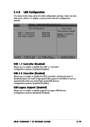
...USB support in the BIOS to turn on automatically when you install high speed USB devices. Setting this menu show the USB configuration settings. Configuration options: [Enabled] Disabled] USB 2.0 Controller [Enabled] Allows you to enable or disable the EHCI controller. USB Configuration USB 1.1 Controller USB 2.0 Controller USB Legacy Support [Enabled] [Enabled] [Enabled] Select Menu Item Specific Help Enable or Disable the USB 1.1 Controller. Configuration options: [Enabled] Disabled] USB Legacy Support [Enabled] Allows you to enable or disable support for legacy USB devices...
...USB support in the BIOS to turn on automatically when you install high speed USB devices. Setting this menu show the USB configuration settings. Configuration options: [Enabled] Disabled] USB 2.0 Controller [Enabled] Allows you to enable or disable the EHCI controller. USB Configuration USB 1.1 Controller USB 2.0 Controller USB Legacy Support [Enabled] [Enabled] [Enabled] Select Menu Item Specific Help Enable or Disable the USB 1.1 Controller. Configuration options: [Enabled] Disabled] USB Legacy Support [Enabled] Allows you to enable or disable support for legacy USB devices...

Terminator C3V User Manual
Page 83
5.5.1 APM Configuration This menu shows the Advanced Power Management (APM) configuration settings. Select an item then press to display a pop-up menu with the configuration options. APM Configuration PS2KB Wakeup Select PS2KB Wakeup Password PS2KB Wakeup from S3/S4/S5 PS2MS Wakeup from S3/S4/S5 USB Resume from S3/S4 Power Up On PCI Devices Modem Ring Resume Power On By RTC Alarm x Date of Month x Resume Time(hh:mm:ss) Restore on AC Power Loss PWR Button
5.5.1 APM Configuration This menu shows the Advanced Power Management (APM) configuration settings. Select an item then press to display a pop-up menu with the configuration options. APM Configuration PS2KB Wakeup Select PS2KB Wakeup Password PS2KB Wakeup from S3/S4/S5 PS2MS Wakeup from S3/S4/S5 USB Resume from S3/S4 Power Up On PCI Devices Modem Ring Resume Power On By RTC Alarm x Date of Month x Resume Time(hh:mm:ss) Restore on AC Power Loss PWR Button
Terminator C3V User Manual
Page 93
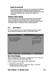
... the BIOS setup default settings, save and exit • type [N], then press , or simply press , to cancel the command and return to require the password before entering the BIOS Setup. Select [System] to the Exit menu ASUS Terminator 1 C3 barebone system 5-31 Exit & Save Changes Exit & Discard Changes Load Setup Default Discard Changes Select Menu Item Specific Help This option saves data to section "2.6 Jumpers" for instructions. The RAM data containing the password information is powered...
... the BIOS setup default settings, save and exit • type [N], then press , or simply press , to cancel the command and return to require the password before entering the BIOS Setup. Select [System] to the Exit menu ASUS Terminator 1 C3 barebone system 5-31 Exit & Save Changes Exit & Discard Changes Load Setup Default Discard Changes Select Menu Item Specific Help This option saves data to section "2.6 Jumpers" for instructions. The RAM data containing the password information is powered...


