
Terminator C3V User Manual
Page 3
... a hard disk drive 2-13 2.9 Re-connecting cables 2-15 2.9.1 LED cables 2-15 2.9.2 UAEX module 2-16 2.10 Replacing the cover 2-17 2.11 Connecting external devices 2-19 2.12 Power supply specifications 2-20 2.12.1 Input Characteristics 2-20 2.12.2 Output Characteristics 2-20 2.12.3 Over-Voltage Protection (OVP 2-20 iii
... a hard disk drive 2-13 2.9 Re-connecting cables 2-15 2.9.1 LED cables 2-15 2.9.2 UAEX module 2-16 2.10 Replacing the cover 2-17 2.11 Connecting external devices 2-19 2.12 Power supply specifications 2-20 2.12.1 Input Characteristics 2-20 2.12.2 Output Characteristics 2-20 2.12.3 Over-Voltage Protection (OVP 2-20 iii
Terminator C3V User Manual
Page 7
... empfohlenem ähnljchen Typ. Entsorgung gebrauchter Batterien nach Angaben des Herstellers. Safety information Electrical safety • To prevent electrical shock hazard, disconnect the power cable from the electrical outlet before the signal cables are not damaged. Operation safety • Before installing devices into the system, carefully read all ... from the system, ensure that came with the package. • Before using the product, make sure all cables are correctly connected and the power cables are connected. • If the power supply is incorrectly replaced.
... empfohlenem ähnljchen Typ. Entsorgung gebrauchter Batterien nach Angaben des Herstellers. Safety information Electrical safety • To prevent electrical shock hazard, disconnect the power cable from the electrical outlet before the signal cables are not damaged. Operation safety • Before installing devices into the system, carefully read all ... from the system, ensure that came with the package. • Before using the product, make sure all cables are correctly connected and the power cables are connected. • If the power supply is incorrectly replaced.
Terminator C3V User Manual
Page 12
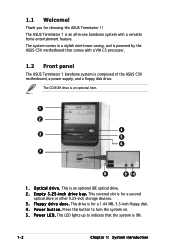
... system comes in -one barebone system with a VIA C3 processor. 1.2 Front panel The ASUS Terminator 1 barebone system is ON. 1-2 Chapter 1: System introduction i n c h d r i v e b a y . The ASUS Terminator 1 is an all-in a stylish mini-tower casing, and is powered by the ASUS C3V motherboard that the system is composed of the ASUS C3V motherboard, a power supply, and a floppy disk drive. This drive is...
... system comes in -one barebone system with a VIA C3 processor. 1.2 Front panel The ASUS Terminator 1 barebone system is ON. 1-2 Chapter 1: System introduction i n c h d r i v e b a y . The ASUS Terminator 1 is an all-in a stylish mini-tower casing, and is powered by the ASUS C3V motherboard that the system is composed of the ASUS C3V motherboard, a power supply, and a floppy disk drive. This drive is...
Terminator C3V User Manual
Page 15
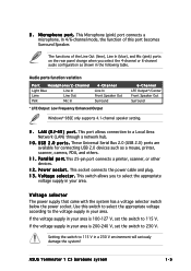
... your area is 100-127 V, set the switch to the voltage supply in your area. M i c r o p h o n e p o r t . This port allows connection to 115 V. This socket connects the power cable and plug. 1 3 . Setting the switch to select the appropriate voltage supply in your area. ASUS Terminator 1 C3 barebone system 1-5 L A N ( R J - 4 5 ) p o r t . P o w e r s o c k e t . Audio ports function variation Port Headphone/2-Channel Light Blue Line...
... your area is 100-127 V, set the switch to the voltage supply in your area. M i c r o p h o n e p o r t . This port allows connection to 115 V. This socket connects the power cable and plug. 1 3 . Setting the switch to select the appropriate voltage supply in your area. ASUS Terminator 1 C3 barebone system 1-5 L A N ( R J - 4 5 ) p o r t . P o w e r s o c k e t . Audio ports function variation Port Headphone/2-Channel Light Blue Line...
Terminator C3V User Manual
Page 16
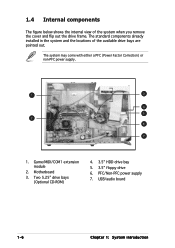
The system may come with either a PFC (Power Factor Correction) or non-PFC power supply. 1 3 4 5 2 6 7 1. Two 5.25" drive bays (Optional CD-ROM) 4. 3.5" HDD drive bay 5. 3.5" floppy drive 6. PFC/Non-PFC power supply 7. The standard components already installed in the system and the locations of the system when you remove the cover and flip out the drive frame. Game/MIDI/COM1 extension module 2. USB/audio board 1-6 Chapter 1: System introduction Motherboard 3. 1.4 Internal components The figure below shows the internal view of the available drive bays are pointed out.
The system may come with either a PFC (Power Factor Correction) or non-PFC power supply. 1 3 4 5 2 6 7 1. Two 5.25" drive bays (Optional CD-ROM) 4. 3.5" HDD drive bay 5. 3.5" floppy drive 6. PFC/Non-PFC power supply 7. The standard components already installed in the system and the locations of the system when you remove the cover and flip out the drive frame. Game/MIDI/COM1 extension module 2. USB/audio board 1-6 Chapter 1: System introduction Motherboard 3. 1.4 Internal components The figure below shows the internal view of the available drive bays are pointed out.

Terminator C3V User Manual
Page 18
...install components into the system. • Use a grounded wrist strap or touch a safely grounded object or a metal object, such as the power supply case, before installing any component, place it on them due to static electricity. • Hold components by the edges to indicate that the... DDR Dual Inline Memory Module (DIMM) 2. Expansion card(s) 3. The motherboard comes with the component. Hard disk drive 4. Unplug the power cable from the power outlet and make sure that you have all the components that you plan to install 1. This LED lights up to avoid touching the ...
...install components into the system. • Use a grounded wrist strap or touch a safely grounded object or a metal object, such as the power supply case, before installing any component, place it on them due to static electricity. • Hold components by the edges to indicate that the... DDR Dual Inline Memory Module (DIMM) 2. Expansion card(s) 3. The motherboard comes with the component. Hard disk drive 4. Unplug the power cable from the power outlet and make sure that you have all the components that you plan to install 1. This LED lights up to avoid touching the ...
Terminator C3V User Manual
Page 28
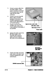
... ribbon cable to the black 4-pin connector labeled CD on the motherboard. 9. Secondary IDE connector (SEC_IDE) CD-ROM connector (CD) 2-12 Chapter 2: Basic Installation Connect a power cable from the power supply to the power connector at the back of the IDE ribbon cable to Pin...
... ribbon cable to the black 4-pin connector labeled CD on the motherboard. 9. Secondary IDE connector (SEC_IDE) CD-ROM connector (CD) 2-12 Chapter 2: Basic Installation Connect a power cable from the power supply to the power connector at the back of the IDE ribbon cable to Pin...

Terminator C3V User Manual
Page 30
Connect one end of the IDE hard disk ribbon cable to the IDE interface at the back of the HDD. Connect the other end of the HDD, matching the red stripe on the motherboard. Use the cable with Pin 1 on the IDE interface. Red stripe to the primary IDE connector (blue connector labeled PRI_IDE) on the cable with the white connector. 6. 5. Primary IDE connector (PRI_IDE) 2-14 Chapter 2: Basic Installation Connect a power cable from the power supply to the power connector at the back of the IDE ribbon cable to Pin 1 IDE ribbon cable Power cable 7.
Connect one end of the IDE hard disk ribbon cable to the IDE interface at the back of the HDD. Connect the other end of the HDD, matching the red stripe on the motherboard. Use the cable with Pin 1 on the IDE interface. Red stripe to the primary IDE connector (blue connector labeled PRI_IDE) on the cable with the white connector. 6. 5. Primary IDE connector (PRI_IDE) 2-14 Chapter 2: Basic Installation Connect a power cable from the power supply to the power connector at the back of the IDE ribbon cable to Pin 1 IDE ribbon cable Power cable 7.
Terminator C3V User Manual
Page 31
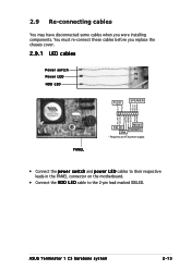
ASUS Terminator 1 C3 barebone system 2-15 You must re-connect these cables before you were installing components. ExtSMI# Ground PWRBIN Ground Reset Ground PANEL RESET IDELED PWRBTN SMI * Requires an ATX power supply. • Connect the power switch and power LED cables to their respective leads in the PANEL connector on the motherboard. • Connect the H D D L E D cable to...
ASUS Terminator 1 C3 barebone system 2-15 You must re-connect these cables before you were installing components. ExtSMI# Ground PWRBIN Ground Reset Ground PANEL RESET IDELED PWRBTN SMI * Requires an ATX power supply. • Connect the power switch and power LED cables to their respective leads in the PANEL connector on the motherboard. • Connect the H D D L E D cable to...

Terminator C3V User Manual
Page 36
...50mVp-p 120mVp-p 120mVp-p 50mVp-p 50mVp-p 2.12.3 Over-Voltage Protection (OVP) Output Voltage Maximum Voltage +5V 6.5V +12V 15.6V +3.3V 4.3V The power supply will shut down or automatically recover when the fault condition is removed. 2-20 Chapter 2: Basic Installation at 230Vac, maximum load Inrush Current 90A max. at... 25°C Efficiency 70% min. By shorting +5VSB, the power supply can latch down and latch off for shorting +5V, +12V, -12V, or +3.3V. at 115Vac, full load cold start at 115Vac ...
...50mVp-p 120mVp-p 120mVp-p 50mVp-p 50mVp-p 2.12.3 Over-Voltage Protection (OVP) Output Voltage Maximum Voltage +5V 6.5V +12V 15.6V +3.3V 4.3V The power supply will shut down or automatically recover when the fault condition is removed. 2-20 Chapter 2: Basic Installation at 230Vac, maximum load Inrush Current 90A max. at... 25°C Efficiency 70% min. By shorting +5VSB, the power supply can latch down and latch off for shorting +5V, +12V, -12V, or +3.3V. at 115Vac, full load cold start at 115Vac ...

Terminator C3V User Manual
Page 53
...) USBPWR34 USBPWR56 USBPWR78 12 23 +5V +5VSB (Default) ASUS Terminator T1 C3 barebone system 4-3 4.3 Jumpers This section describes and illustrates the jumpers on the motherboard. 1 . The USBPWR12 jumper is for all devices requiring +5VSB power. Set to +5VSB to CPU, DRAM in slow refresh, power supply in reduced power mode). The USBPWR34, USBPWR56, and USBPWR78 jumpers are...
...) USBPWR34 USBPWR56 USBPWR78 12 23 +5V +5VSB (Default) ASUS Terminator T1 C3 barebone system 4-3 4.3 Jumpers This section describes and illustrates the jumpers on the motherboard. 1 . The USBPWR12 jumper is for all devices requiring +5VSB power. Set to +5VSB to CPU, DRAM in slow refresh, power supply in reduced power mode). The USBPWR34, USBPWR56, and USBPWR78 jumpers are...
Terminator C3V User Manual
Page 57
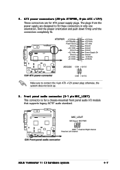
...® C3V ATXPWR +12.0Volts +5V Standby Power Good Ground +5.0 Volts Ground +5.0 Volts Ground +3.3 Volts +3.3 Volts +5.0 Volts +5.0 Volts -5.0 Volts Ground Ground Ground Power Supply On Ground -12.0Volts +3.3Volts ATX12V COM +12V DC C3V ATX power connector COM +12V DC Make sure to fit ... power supply plugs. The plugs from the power supply are for a chassis-mounted front panel audio I/O module that supports legacy AC'97 audio standard. ® C3V MIC_LOUT MIC Signal MIC PWR 1 GND Head set Right channel Head set Left channel C3V Front panel audio connector ASUS Terminator T1 C3...
...® C3V ATXPWR +12.0Volts +5V Standby Power Good Ground +5.0 Volts Ground +5.0 Volts Ground +3.3 Volts +3.3 Volts +5.0 Volts +5.0 Volts -5.0 Volts Ground Ground Ground Power Supply On Ground -12.0Volts +3.3Volts ATX12V COM +12V DC C3V ATX power connector COM +12V DC Make sure to fit ... power supply plugs. The plugs from the power supply are for a chassis-mounted front panel audio I/O module that supports legacy AC'97 audio standard. ® C3V MIC_LOUT MIC Signal MIC PWR 1 GND Head set Right channel Head set Left channel C3V Front panel audio connector ASUS Terminator T1 C3...

Terminator C3V User Manual
Page 61
...) [optional] These connectors are for IEEE 1394a ports. ExtSMI# Ground PWRBIN Ground Reset Ground C3V System panel connectors RESET IDELED PWRBTN SMI * Requires an ATX power supply. Doing so will damage the motherboard! 13. ASUS Terminator T1 C3 barebone system 4-11 12.
...) [optional] These connectors are for IEEE 1394a ports. ExtSMI# Ground PWRBIN Ground Reset Ground C3V System panel connectors RESET IDELED PWRBTN SMI * Requires an ATX power supply. Doing so will damage the motherboard! 13. ASUS Terminator T1 C3 barebone system 4-11 12.

Terminator C3V User Manual
Page 83
APM Configuration PS2KB Wakeup Select PS2KB Wakeup Password PS2KB Wakeup from S3/S4/S5 PS2MS Wakeup from S3/S4/S5 USB Resume from S3/S4 Power Up On PCI Devices Modem Ring Resume Power On By RTC Alarm x Date of Month x Resume Time(hh:mm:ss) Restore on AC Power Loss PWR Button Select an item then press to display a pop-up menu with the configuration options. 5.5.1 APM Configuration This menu shows the Advanced Power Management (APM) configuration settings.
APM Configuration PS2KB Wakeup Select PS2KB Wakeup Password PS2KB Wakeup from S3/S4/S5 PS2MS Wakeup from S3/S4/S5 USB Resume from S3/S4 Power Up On PCI Devices Modem Ring Resume Power On By RTC Alarm x Date of Month x Resume Time(hh:mm:ss) Restore on AC Power Loss PWR Button Select an item then press to display a pop-up menu with the configuration options. 5.5.1 APM Configuration This menu shows the Advanced Power Management (APM) configuration settings.
Terminator C3V User Manual
Page 86
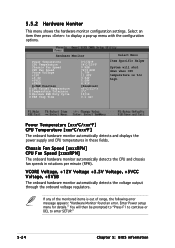
...range, the following error message appears: "Hardware Monitor found an error. Power Temperature [xxxoC/xxxoF ] CPU Temperature [xxxoC/xxxoF ] The onboard hardware monitor automatically detects and displays the power supply and CPU temperatures in rotations per minute (RPM). Chassis Fan Speed [...3V Voltage, +5VCC Voltage, +5VSB The onboard hardware monitor automatically detects the voltage output through the onboard voltage regulators. Enter Power setup menu for details." 5.5.2 Hardware Monitor This menu shows the hardware monitor configuration settings. Select an item then press to ...
...range, the following error message appears: "Hardware Monitor found an error. Power Temperature [xxxoC/xxxoF ] CPU Temperature [xxxoC/xxxoF ] The onboard hardware monitor automatically detects and displays the power supply and CPU temperatures in rotations per minute (RPM). Chassis Fan Speed [...3V Voltage, +5VCC Voltage, +5VSB The onboard hardware monitor automatically detects the voltage output through the onboard voltage regulators. Enter Power setup menu for details." 5.5.2 Hardware Monitor This menu shows the hardware monitor configuration settings. Select an item then press to ...


