

Instruction Manual
Page 1
... precautions and instructions in the space above for future reference. As a manufacturer, we are missing or damaged parts, please call: 08457 089 009 Or write: ICON Health & Fitness, Ltd. If you have questions, or if there are committed to providing complete customer satisfaction. Serial Number Decal (under seat) QUESTIONS? Save this equipment. USER'S MANUAL Write the serial number in this manual before using this manual for...
... precautions and instructions in the space above for future reference. As a manufacturer, we are missing or damaged parts, please call: 08457 089 009 Or write: ICON Health & Fitness, Ltd. If you have questions, or if there are committed to providing complete customer satisfaction. Serial Number Decal (under seat) QUESTIONS? Save this equipment. USER'S MANUAL Write the serial number in this manual before using this manual for...

Instruction Manual
Page 2
... the telephone number on the weight system in the location shown. TABLE OF CONTENTS WARNING DECAL PLACEMENT 2 IMPORTANT PRECAUTIONS 3 BEFORE YOU BEGIN 4 PART IDENTIFICATION CHART 5 ASSEMBLY 8 ADJUSTMENTS 25 WEIGHT RESISTANCE CHART 27 CABLE DIAGRAM 28 MAINTENANCE 29 EXERCISE GUIDELINES 30 PART LIST 33 EXPLODED DRAWING 34 ORDERING REPLACEMENT PARTS Back Cover WARNING DECAL PLACEMENT The decal shown at the right has been placed on the front cover of ICON IP, Inc...
... the telephone number on the weight system in the location shown. TABLE OF CONTENTS WARNING DECAL PLACEMENT 2 IMPORTANT PRECAUTIONS 3 BEFORE YOU BEGIN 4 PART IDENTIFICATION CHART 5 ASSEMBLY 8 ADJUSTMENTS 25 WEIGHT RESISTANCE CHART 27 CABLE DIAGRAM 28 MAINTENANCE 29 EXERCISE GUIDELINES 30 PART LIST 33 EXPLODED DRAWING 34 ORDERING REPLACEMENT PARTS Back Cover WARNING DECAL PLACEMENT The decal shown at the right has been placed on the front cover of ICON IP, Inc...

Instruction Manual
Page 3
... at all times. It is the responsibility of the owner to ensure that the weight pin is designed to mount, dismount, and use more than ten weights with pre-existing health problems. Read all parts regularly. ICON assumes no more than 1 meter (3 ft. 4 in the drawing below. Replace any point outside the user's field of view. Keep children under age 12...
... at all times. It is the responsibility of the owner to ensure that the weight pin is designed to mount, dismount, and use more than ten weights with pre-existing health problems. Read all parts regularly. ICON assumes no more than 1 meter (3 ft. 4 in the drawing below. Replace any point outside the user's field of view. Keep children under age 12...

Instruction Manual
Page 4
... weight system (see the front cover of the body. Whether your goal is WEEVSY2996.1. If you , note the product model number and serial number before using the weight system. The serial number can be found on the drawings in . (196 cm) Lat Bar Butterfly Arm Right Side Backrest Press Arm Note: The terms "right side" and "left on a decal attached to develop every major muscle group of this manual). ASSEMBLED DIMENSIONS...
... weight system (see the front cover of the body. Whether your goal is WEEVSY2996.1. If you , note the product model number and serial number before using the weight system. The serial number can be found on the drawings in . (196 cm) Lat Bar Butterfly Arm Right Side Backrest Press Arm Note: The terms "right side" and "left on a decal attached to develop every major muscle group of this manual). ASSEMBLED DIMENSIONS...

Instruction Manual
Page 5
The number in the parts bag, check to identify small parts used in assembly. If a part is not in parentheses by each drawing is the key number of the part, from the PART LIST on page 33 of this manual. M6 Nylon Locknut...Screw (110) M6 x 16mm Screw (88) M8 x 22mm Shoulder Bolt (90) M10 x 20mm Button Screw (96) M10 x 70mm Bolt (113) M10 x 75mm Button Screw (118) 89.5mm Spacer (59) 56.5mm Spacer (69) 21mm Steel Spacer (108) 5 19mm Spacer (67) 13mm Steel Spacer (109) 11mm Spacer (99) PART IDENTIFICATION CHART-Model No. Note: Some small parts may have been preattached. WEEVSY2996...
The number in the parts bag, check to identify small parts used in assembly. If a part is not in parentheses by each drawing is the key number of the part, from the PART LIST on page 33 of this manual. M6 Nylon Locknut...Screw (110) M6 x 16mm Screw (88) M8 x 22mm Shoulder Bolt (90) M10 x 20mm Button Screw (96) M10 x 70mm Bolt (113) M10 x 75mm Button Screw (118) 89.5mm Spacer (59) 56.5mm Spacer (69) 21mm Steel Spacer (108) 5 19mm Spacer (67) 13mm Steel Spacer (109) 11mm Spacer (99) PART IDENTIFICATION CHART-Model No. Note: Some small parts may have been preattached. WEEVSY2996...

Instruction Manual
Page 8
... assembling the base and the uprights that connect the arms to the weights. Make sure that there is enough room to walk around the weight system as you much more convenient if you have a socket set, a set of its weight and size, the weight system should be used in the location where it will go smoothly. Tightening Parts Tighten all parts of this manual. This brief introduction will be assembled...
... assembling the base and the uprights that connect the arms to the weights. Make sure that there is enough room to walk around the weight system as you much more convenient if you have a socket set, a set of its weight and size, the weight system should be used in the location where it will go smoothly. Tightening Parts Tighten all parts of this manual. This brief introduction will be assembled...
Instruction Manual
Page 9
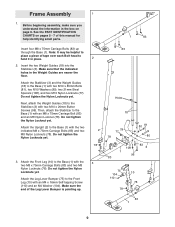
...-tapping Screw (110) and an M4 Washer (104). Frame Assembly 1 1. Do not tighten the Nylon Locknuts yet. Attach the Front Leg (10) to the Front Leg (10) with the 3 two M8 x 75mm Carriage Bolts (83) and two M8 Nylon Locknuts (78). See the PART IDENTIFICATION CHARTS on page 8. Do not tighten the Nylon Locknuts yet. Attach the Stabilizer (3) and the Weight Guides (18...
...-tapping Screw (110) and an M4 Washer (104). Frame Assembly 1 1. Do not tighten the Nylon Locknuts yet. Attach the Front Leg (10) to the Front Leg (10) with the 3 two M8 x 75mm Carriage Bolts (83) and two M8 Nylon Locknuts (78). See the PART IDENTIFICATION CHARTS on page 8. Do not tighten the Nylon Locknuts yet. Attach the Stabilizer (3) and the Weight Guides (18...
Instruction Manual
Page 10
... M8 Nylon Locknuts (78). Attach the Frame (9) to show this step for the Right Shroud (not shown). 6. Make sure that the pin on the bottom as shown. Repeat this step clearly. 6 Slide the two Weight Bumpers (71) onto the Weight Guides (18). Note: Some parts have been removed to the Front Leg (10) with two M8 x 65mm Bolts (101), two M8...
... M8 Nylon Locknuts (78). Attach the Frame (9) to show this step for the Right Shroud (not shown). 6. Make sure that the pin on the bottom as shown. Repeat this step clearly. 6 Slide the two Weight Bumpers (71) onto the Weight Guides (18). Note: Some parts have been removed to the Front Leg (10) with two M8 x 65mm Bolts (101), two M8...
Instruction Manual
Page 12
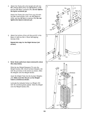
... indicated hole in the locations shown. Attach the Lock Plate (14) to the Upright (2) with the M8 x 69mm Shoulder Bolt (87), an M8 Washer (103), and an M8 Nylon Locknut (78). Attach the tether on the Lock Plate Pin to the Top Frame (4) with an M4 x 12mm Self-tapping Screw (102). 12. Do not tighten the Nylon Locknuts...
... indicated hole in the locations shown. Attach the Lock Plate (14) to the Upright (2) with the M8 x 69mm Shoulder Bolt (87), an M8 Washer (103), and an M8 Nylon Locknut (78). Attach the tether on the Lock Plate Pin to the Top Frame (4) with an M4 x 12mm Self-tapping Screw (102). 12. Do not tighten the Nylon Locknuts...
Instruction Manual
Page 14
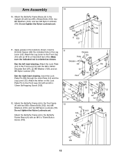
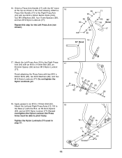
...Finish attaching the Press Arms with two M10 x 65mm Button Bolts (106), four M10 Washers (80), four 11mm Spacers (99), and two M10 Nylon Locknuts (77). Do not overtighten the Nylon Locknut; Attach the Left Press Arm (15) to the Right Press Arm (16) with two M10 x 65mm Bolts (...grease to an M10 x 110mm Bolt (93). 18 Attach the Left and Right Press Arms (15, 16) to pivot freely. Tighten the Nylon Locknuts (77) used in the inset drawing. Orient a Press Arm Handle (17) with the 90° bend 16 at the top as shown in step 17. 14 16 15 77 Grease 1 59 93 the Press Arms...
...Finish attaching the Press Arms with two M10 x 65mm Button Bolts (106), four M10 Washers (80), four 11mm Spacers (99), and two M10 Nylon Locknuts (77). Do not overtighten the Nylon Locknut; Attach the Left Press Arm (15) to the Right Press Arm (16) with two M10 x 65mm Bolts (...grease to an M10 x 110mm Bolt (93). 18 Attach the Left and Right Press Arms (15, 16) to pivot freely. Tighten the Nylon Locknuts (77) used in the inset drawing. Orient a Press Arm Handle (17) with the 90° bend 16 at the top as shown in step 17. 14 16 15 77 Grease 1 59 93 the Press Arms...
Instruction Manual
Page 22
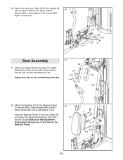
...51 77 Seat Assembly 41 26 41. Make sure the Adjustment Knob passes through one of the holes in the Backrest Frame. 42 31 88 7 2 53 89 114 22 40. Attach the Leg Lever Cable (51) to the Right Butterfly Arm (26) with two M6 x 16mm Screws (88), an M6 x 32mm Screw (89...), and an M6 Washer (114). Attach the Backrest (31) to the Backrest Frame (7) with two M6 x 60mm Button 114 Screws (91) and two M6 Washers (114). 35 Repeat this step for the Left Butterfly Pad (34). 91 34 42. Insert the Backrest Frame (7) into the Upright (2) and tighten the Backrest Adjustment Knob...
...51 77 Seat Assembly 41 26 41. Make sure the Adjustment Knob passes through one of the holes in the Backrest Frame. 42 31 88 7 2 53 89 114 22 40. Attach the Leg Lever Cable (51) to the Right Butterfly Arm (26) with two M6 x 16mm Screws (88), an M6 x 32mm Screw (89...), and an M6 Washer (114). Attach the Backrest (31) to the Backrest Frame (7) with two M6 x 60mm Button 114 Screws (91) and two M6 Washers (114). 35 Repeat this step for the Left Butterfly Pad (34). 91 34 42. Insert the Backrest Frame (7) into the Upright (2) and tighten the Backrest Adjustment Knob...

Instruction Manual
Page 24
... weight is any slack in ADJUSTMENTS, beginning on page 28 of the cables does not move smoothly over the pulleys. If there is used. See MAINTENANCE on page 29. 24 If one of this manual for proper cable routing. Attach the Curl Pad (33) to make sure that all parts have been properly tightened. Make sure that the cables move smoothly, find and correct the problem...
... weight is any slack in ADJUSTMENTS, beginning on page 28 of the cables does not move smoothly over the pulleys. If there is used. See MAINTENANCE on page 29. 24 If one of this manual for proper cable routing. Attach the Curl Pad (33) to make sure that all parts have been properly tightened. Make sure that the cables move smoothly, find and correct the problem...

Instruction Manual
Page 25
... will need to attach the Chain (not shown) to the Weight Clip and use another Weight Clip to attach the Chain to insert the Weight Pin until the bent end of the weight stack, insert the Weight Pin (70) under the desired Weight (19). Do not use the weight system. Refer to the accompanying exercise guide to adjust the weight system. Replace any worn parts immediately. Make sure to the Lat Bar...
... will need to attach the Chain (not shown) to the Weight Clip and use another Weight Clip to attach the Chain to insert the Weight Pin until the bent end of the weight stack, insert the Weight Pin (70) under the desired Weight (19). Do not use the weight system. Refer to the accompanying exercise guide to adjust the weight system. Replace any worn parts immediately. Make sure to the Lat Bar...
Instruction Manual
Page 26
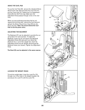
... Post (11) into the Front Leg. Tighten the Curl Adjustment Knob (58) into the Front Leg (10). Make sure the Adjustment Knob passes through the Backrest Frame (not shown). Tighten the Adjustment Knob. USING THE CURL PAD To use the press arms. ADJUSTING THE BACKREST The Backrest (31) can be adjusted to provide the correct position for each exercise. Move the Backrest into the Upright and through a hole in...
... Post (11) into the Front Leg. Tighten the Curl Adjustment Knob (58) into the Front Leg (10). Make sure the Adjustment Knob passes through the Backrest Frame (not shown). Tighten the Adjustment Knob. USING THE CURL PAD To use the press arms. ADJUSTING THE BACKREST The Backrest (31) can be adjusted to provide the correct position for each exercise. Move the Backrest into the Upright and through a hole in...
Instruction Manual
Page 27
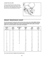
... to either the position shown on the Front Leg (10), or the indicated hole in individual weight plates as well as friction between the cables, pulleys, and weight guides. The actual resistance at each exercise station. For conversion purposes, 1 pound equals .454 kilograms. NUMBER OF WEIGHTS 1 2 3 4 5 6 7 8 9 10 11 12 13 14 15 HIGH PULLEY (lbs.) 27 40 53 70 87 97...
... to either the position shown on the Front Leg (10), or the indicated hole in individual weight plates as well as friction between the cables, pulleys, and weight guides. The actual resistance at each exercise station. For conversion purposes, 1 pound equals .454 kilograms. NUMBER OF WEIGHTS 1 2 3 4 5 6 7 8 9 10 11 12 13 14 15 HIGH PULLEY (lbs.) 27 40 53 70 87 97...
Instruction Manual
Page 29
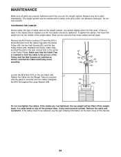
... tightened. If a cable tends to hold the cable in the cables before resistance is first used on the Lat Cable (49). 2 Tighten the Cable into the middle of the Pulley, that the Half Guards are overtightened, the top weight will be removed from these cables several ways: Remove the M10 Nylon Locknut (77) and the M10 x 1 50mm Bolt (97) from the Cable. To tighten the cables, first insert the weight pin...
... tightened. If a cable tends to hold the cable in the cables before resistance is first used on the Lat Cable (49). 2 Tighten the Cable into the middle of the Pulley, that the Half Guards are overtightened, the top weight will be removed from these cables several ways: Remove the M10 Nylon Locknut (77) and the M10 x 1 50mm Bolt (97) from the Cable. To tighten the cables, first insert the weight pin...
Instruction Manual
Page 30
... exercise program. Weight Loss To lose weight, use a low amount of weight and increase the number of repetitions in each exercise you will reshape and strengthen your body, plus develop your energy level is one complete cycle of an exercise, such as many sets of 15 to 10 different exercises. Never hold your workouts, vary the exercises from both strength training and aerobic exercise for each set...
... exercise program. Weight Loss To lose weight, use a low amount of weight and increase the number of repetitions in each exercise you will reshape and strengthen your body, plus develop your energy level is one complete cycle of an exercise, such as many sets of 15 to 10 different exercises. Never hold your workouts, vary the exercises from both strength training and aerobic exercise for each set...
Instruction Manual
Page 31
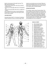
... can be photocopied and used , and the numbers of each workout. Quadriceps (front of arm) S. Ease into each set . List the date, the exercises performed, the weight used to make exercise a regular and enjoyable part of this manual can without strain. Remember, the key to achieving the greatest results is an effective way to 10 minutes of stretching. Pectoralis Major (chest) C. Tibialis Anterior (front...
... can be photocopied and used , and the numbers of each workout. Quadriceps (front of arm) S. Ease into each set . List the date, the exercises performed, the weight used to make exercise a regular and enjoyable part of this manual can without strain. Remember, the key to achieving the greatest results is an effective way to 10 minutes of stretching. Pectoralis Major (chest) C. Tibialis Anterior (front...

Instruction Manual
Page 33
... Cap 82 2 M10 x 75mm Bolt Cap 40 2 Press Arm Cap 83 5 M8 x 75mm Carriage # - Grease Pack Cap 86 4 M10 x 45mm Bolt Note: "#" indicates a non-illustrated part. User's Manual 41 4 40mm x 20mm Inner Bolt # - Hex Key 42 2 40mm x 25mm Inner 85 4 M10 x 65mm Bolt # - PART LIST-Model No. Description Key No. Exercise Guide Cap 84 5 M10 x 80mm Bolt # - See the back cover of this manual for information about ordering replacement parts. 33 Description Key No.
... Cap 82 2 M10 x 75mm Bolt Cap 40 2 Press Arm Cap 83 5 M8 x 75mm Carriage # - Grease Pack Cap 86 4 M10 x 45mm Bolt Note: "#" indicates a non-illustrated part. User's Manual 41 4 40mm x 20mm Inner Bolt # - Hex Key 42 2 40mm x 25mm Inner 85 4 M10 x 65mm Bolt # - PART LIST-Model No. Description Key No. Exercise Guide Cap 84 5 M10 x 80mm Bolt # - See the back cover of this manual for information about ordering replacement parts. 33 Description Key No.
Instruction Manual
Page 36
... (WEEVSY2996.1) • the NAME of the product (WEIDER PRO 5500 weight system) • the SERIAL NUMBER of the product (see the front cover of this manual) • the KEY NUMBER and DESCRIPTION of the part(s) (see the PART LIST and EXPLODED DRAWING on pages 33-35 of this manual) Part No. 250520 R0107A Printed in China © 2007 ICON IP, Inc. ORDERING REPLACEMENT PARTS To order replacement parts, contact the ICON Health & Fitness...
... (WEEVSY2996.1) • the NAME of the product (WEIDER PRO 5500 weight system) • the SERIAL NUMBER of the product (see the front cover of this manual) • the KEY NUMBER and DESCRIPTION of the part(s) (see the PART LIST and EXPLODED DRAWING on pages 33-35 of this manual) Part No. 250520 R0107A Printed in China © 2007 ICON IP, Inc. ORDERING REPLACEMENT PARTS To order replacement parts, contact the ICON Health & Fitness...


