
Uk Manual
Page 1
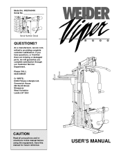
... committed to providing complete customer satisfaction. Model No. WESY60400 Serial No. Serial Number Decal QUESTIONS? If you complete satisfaction through our Customer Service Department. Please CALL: 0345-089009 Or WRITE: ICON Fitness Lifestyle Ltd. Greenwich House 223 North Street Sheepscar West Yorkshire Leeds LS7 2AA CAUTION Read all precautions and instructions in this manual before using this manual for future reference. USER'S MANUAL
... committed to providing complete customer satisfaction. Model No. WESY60400 Serial No. Serial Number Decal QUESTIONS? If you complete satisfaction through our Customer Service Department. Please CALL: 0345-089009 Or WRITE: ICON Fitness Lifestyle Ltd. Greenwich House 223 North Street Sheepscar West Yorkshire Leeds LS7 2AA CAUTION Read all precautions and instructions in this manual before using this manual for future reference. USER'S MANUAL
Uk Manual
Page 2
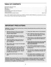
... before beginning assembly. Never release the press arms, leg lever, lat bar or nylon strap whilst weights are raised. The resistance cylinders become very hot during use of this treadmill in -home use only. Keep hands and feet away from the weight system at all parts each use the lat bar. 11. Keep children under 12 away from moving parts. 13. ICON assumes no responsibility for in any time whilst exercising, stop immediately...
... before beginning assembly. Never release the press arms, leg lever, lat bar or nylon strap whilst weights are raised. The resistance cylinders become very hot during use of this treadmill in -home use only. Keep hands and feet away from the weight system at all parts each use the lat bar. 11. Keep children under 12 away from moving parts. 13. ICON assumes no responsibility for in any time whilst exercising, stop immediately...
Uk Manual
Page 3
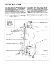
... versatile WEIDER® VIPER 2000. Before reading further, please review the drawing below and familiarise yourself with the parts that are labelled. High Pulley Station Lat Bar Arms VKR Arms Backrest Resistance Cylinders Stepper Weight Stack Weight Pin Leg Lever Low Pulley Station Foot Plate 3 The model number is to tone your body, build dramatic muscle size and strength, or improve your benefit, read this user's manual). To help you want. ASSEMBLED DIMENSIONS: Height...
... versatile WEIDER® VIPER 2000. Before reading further, please review the drawing below and familiarise yourself with the parts that are labelled. High Pulley Station Lat Bar Arms VKR Arms Backrest Resistance Cylinders Stepper Weight Stack Weight Pin Leg Lever Low Pulley Station Foot Plate 3 The model number is to tone your body, build dramatic muscle size and strength, or improve your benefit, read this user's manual). To help you want. ASSEMBLED DIMENSIONS: Height...
Uk Manual
Page 4
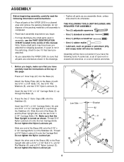
... Locknut (3) onto the Carriage Bolt. Note: Some small parts may have the following information and instructions: • Place all parts as grease or petroleum jelly, and soapy water will be more convenient if you assemble the VIPER 2000, be needed. Do not tighten the Nylon Locknuts yet. ASSEMBLY Before beginning assembly, carefully read the instructions at the top of this manual. Attach the Pulley Plate (20) to...
... Locknut (3) onto the Carriage Bolt. Note: Some small parts may have the following information and instructions: • Place all parts as grease or petroleum jelly, and soapy water will be more convenient if you assemble the VIPER 2000, be needed. Do not tighten the Nylon Locknuts yet. ASSEMBLY Before beginning assembly, carefully read the instructions at the top of this manual. Attach the Pulley Plate (20) to...

Uk Manual
Page 5
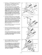
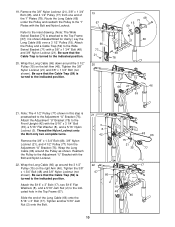
... Locknuts used in steps 2 through 4. 42 82 5 Do not tighten the Nylon Locknut yet. Attach the Top Frame (67) to the Stop Bracket (63) with a 5/16" x 1 1/2" Bolt (24) and 5/16" Nylon Locknut (3). Slide the Front Upright (42) onto the two 5/16" x 2 1/2" Carriage Bolts (1) in the Stop Bracket (63) with a 5/16" x 2 3/4" Bolt (11), 5/16" Flat Washer (8), and 5/16" Nylon Locknut (3). Press the...
... Locknuts used in steps 2 through 4. 42 82 5 Do not tighten the Nylon Locknut yet. Attach the Top Frame (67) to the Stop Bracket (63) with a 5/16" x 1 1/2" Bolt (24) and 5/16" Nylon Locknut (3). Slide the Front Upright (42) onto the two 5/16" x 2 1/2" Carriage Bolts (1) in the Stop Bracket (63) with a 5/16" x 2 3/4" Bolt (11), 5/16" Flat Washer (8), and 5/16" Nylon Locknut (3). Press the...
Uk Manual
Page 6
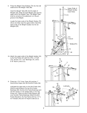
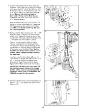
... the Rear Upright (82). Lubricate the pedal axles on the Weight Bumpers (19). Hold a 1" Retainer (54) and 1" Round Cover Cap (55) against the right cylinder axle. Be sure that the Pedals are in the Weight Bumpers with a 1/2" Tap Screw (6). Attach a Resistance Cylinder (91) to the left pedal axles. Set the two Weight Bumpers (19) on the indicated 8 plate on the hook at the lower end...
... the Rear Upright (82). Lubricate the pedal axles on the Weight Bumpers (19). Hold a 1" Retainer (54) and 1" Round Cover Cap (55) against the right cylinder axle. Be sure that the Pedals are in the Weight Bumpers with a 1/2" Tap Screw (6). Attach a Resistance Cylinder (91) to the left pedal axles. Set the two Weight Bumpers (19) on the indicated 8 plate on the hook at the lower end...
Uk Manual
Page 7
... the two Arm Frame Bushings (68). Locate the lower ends of the Weight Tube. Press two 1 3/4" Inner Caps (44) and two 1" Round Inner Caps (49) into the ten Weights (25). Set the Arm Frame Bushings and the Arm Frame on the welded plate on the Arm Frame (52). Attach the Arm Frame Bracket to the Top Frame (67) with four 1/4" x 3/4" Screws (18) and...
... the two Arm Frame Bushings (68). Locate the lower ends of the Weight Tube. Press two 1 3/4" Inner Caps (44) and two 1" Round Inner Caps (49) into the ten Weights (25). Set the Arm Frame Bushings and the Arm Frame on the welded plate on the Arm Frame (52). Attach the Arm Frame Bracket to the Top Frame (67) with four 1/4" x 3/4" Screws (18) and...
Uk Manual
Page 8
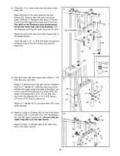
... (3). Attach the Handle with a 3/8" x 2 3/4" Bolt (70), 3/8" Flat Washer 14 (9), and 3/8" Nylon Locknut (21). Slide an Arm (46) onto one of the Handle with soapy water. Tap the Retainers and Round Cover Cap onto the axle. Attach a Large "U" Bracket (56) to the lower axles on the Arm Frame (52). Apply lubricant to one of the axle. Insert the two 4 1/2" "L" Pins...
... (3). Attach the Handle with a 3/8" x 2 3/4" Bolt (70), 3/8" Flat Washer 14 (9), and 3/8" Nylon Locknut (21). Slide an Arm (46) onto one of the Handle with soapy water. Tap the Retainers and Round Cover Cap onto the axle. Attach a Large "U" Bracket (56) to the lower axles on the Arm Frame (52). Apply lubricant to one of the axle. Insert the two 4 1/2" "L" Pins...
Uk Manual
Page 9
15. If the parts shown at the right have a rubber ball. Attach the two "I" Plates (78) to page 19 of the Long Cable (66) that the Cables are properly routed. IMPORTANT: As you assemble the Long Cable (66) and the Short Cable (not shown), refer to two 4 1/2" Pulleys (77) with a 3/8" x 2 3/4" Bolt (70), two 3/8" Flat Washers (9), the two 1/2" x 1/2" Spacers (65), and a 3/8" Nylon...
15. If the parts shown at the right have a rubber ball. Attach the two "I" Plates (78) to page 19 of the Long Cable (66) that the Cables are properly routed. IMPORTANT: As you assemble the Long Cable (66) and the Short Cable (not shown), refer to two 4 1/2" Pulleys (77) with a 3/8" x 2 3/4" Bolt (70), two 3/8" Flat Washers (9), the two 1/2" x 1/2" Spacers (65), and a 3/8" Nylon...
Uk Manual
Page 10
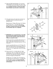
...). Attach the 5/16" x 3" Bolt (17), two 5/16" Flat Washers (8), and a 5/16" Jam Nut (2) to the indicated hole in this step is turned to the indicated position. Wrap the Long Cable (66) down around the 3 1/2" Pulley (15) on the right Arm (46). Tighten the 3/8" x 1 3/4" Bolt (48) and 3/8" Nylon Locknut (not shown). Route the Long Cable (66) under the Pulley and reattach the Pulley to...
...). Attach the 5/16" x 3" Bolt (17), two 5/16" Flat Washers (8), and a 5/16" Jam Nut (2) to the indicated hole in this step is turned to the indicated position. Wrap the Long Cable (66) down around the 3 1/2" Pulley (15) on the right Arm (46). Tighten the 3/8" x 1 3/4" Bolt (48) and 3/8" Nylon Locknut (not shown). Route the Long Cable (66) under the Pulley and reattach the Pulley to...
Uk Manual
Page 11
... a 5/16" x 1 1/2" Bolt (24) through the Weight Guide Bracket (81), Weight Tube, and Short Cable. Remove the 3/8" Nylon Locknut (21), 3/8" x 1 3/4" Bolt (48), and 4 1/2" Pulley (77) from the lower end of the Weight Tube (80). Press the Plastic Flanged Bushing into the upper end of the "I " Plates with a mallet to the "I " Plates (78). Tighten a 5/16" Nylon Locknut (3) onto the Bolt. Refer to the Front Upright as...
... a 5/16" x 1 1/2" Bolt (24) through the Weight Guide Bracket (81), Weight Tube, and Short Cable. Remove the 3/8" Nylon Locknut (21), 3/8" x 1 3/4" Bolt (48), and 4 1/2" Pulley (77) from the lower end of the Weight Tube (80). Press the Plastic Flanged Bushing into the upper end of the "I " Plates with a mallet to the "I " Plates (78). Tighten a 5/16" Nylon Locknut (3) onto the Bolt. Refer to the Front Upright as...
Uk Manual
Page 12
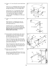
... Leg Lever (29). Attach the Seat Frame with four 1/4" x 3/4" Screws (18). 26. the Leg Lever must be able to the Seat (13) with a 5/16" x 2 3/4" Carriage Bolt (14) and the Seat Knob (40). Insert the two 1/4" x 2" Carriage Bolts (38) into the Left and 29 Right VKR Arms (100, 101). Do not overtighten the Nylon Locknut; Press 1 1/2" Inner Caps (32) into the Seat Frame (36). Tighten...
... Leg Lever (29). Attach the Seat Frame with four 1/4" x 3/4" Screws (18). 26. the Leg Lever must be able to the Seat (13) with a 5/16" x 2 3/4" Carriage Bolt (14) and the Seat Knob (40). Insert the two 1/4" x 2" Carriage Bolts (38) into the Left and 29 Right VKR Arms (100, 101). Do not overtighten the Nylon Locknut; Press 1 1/2" Inner Caps (32) into the Seat Frame (36). Tighten...
Uk Manual
Page 13
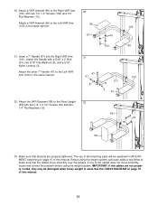
... VKR Arm 31 (101). Make sure that the cables move smoothly over the pulleys. The use of all parts are not properly routed, they may be explained in ADJUSTMENT, beginning on page 19 of this manual. 13 Attach a VKR Armrest (99) to the Rear Upright 32 (82) with two 1/4" x 2" Screws (102) and 1/4" Flat Washers (10). See the CABLE DIAGRAM on page 15 of this manual. 30. Attach...
... VKR Arm 31 (101). Make sure that the cables move smoothly over the pulleys. The use of all parts are not properly routed, they may be explained in ADJUSTMENT, beginning on page 19 of this manual. 13 Attach a VKR Armrest (99) to the Rear Upright 32 (82) with two 1/4" x 2" Screws (102) and 1/4" Flat Washers (10). See the CABLE DIAGRAM on page 15 of this manual. 30. Attach...
Uk Manual
Page 15
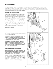
... of resistance at each exercise sta- The weight setting can be adjusted. Refer to the Weight Resistance Chart on the Front Upright (42). For some exercises, the Seat (13) must be removed. Attach the Seat Frame to insert the Weight Pin until the bent end of the Weight Pin is not attached to the leg lever. Next, remove the Seat Knob (40) and 5/16" x 2 3/4" Carriage Bolt (14) from the weight setting. ADJUSTMENT The instructions below describe how each part...
... of resistance at each exercise sta- The weight setting can be adjusted. Refer to the Weight Resistance Chart on the Front Upright (42). For some exercises, the Seat (13) must be removed. Attach the Seat Frame to insert the Weight Pin until the bent end of the Weight Pin is not attached to the leg lever. Next, remove the Seat Knob (40) and 5/16" x 2 3/4" Carriage Bolt (14) from the weight setting. ADJUSTMENT The instructions below describe how each part...

Uk Manual
Page 16
... LOW PULLEY STATION Attach the Lat Bar (85) to be performed. The farther the hooks are fully inserted into the slots in the correct starting position for the exercise to the Short Cable (23) with two Cable Clips. ATTACHING THE LEG LEVER TO THE LOW PULLEY STATION To use . The Nylon Strap (39) can be attached in the same way. CHANGING THE STEPPING RESISTANCE To change the stepping resistance, first...
... LOW PULLEY STATION Attach the Lat Bar (85) to be performed. The farther the hooks are fully inserted into the slots in the correct starting position for the exercise to the Short Cable (23) with two Cable Clips. ATTACHING THE LEG LEVER TO THE LOW PULLEY STATION To use . The Nylon Strap (39) can be attached in the same way. CHANGING THE STEPPING RESISTANCE To change the stepping resistance, first...
Uk Manual
Page 17
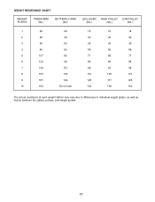
WEIGHT RESISTANCE CHART WEIGHT PLATES PRESS ARM (lbs.) BUTTERFLY ARM (lbs.) LEG LEVER HIGH PULLEY LOW PULLEY (lbs.) (lbs.) (lbs.) 1 29 26 18 16 18 2 48 39 32 30 32 3 69 50 45 43 45 4 83 64 58 56 58 5 107 80 71 68 71 6 129 96 84 80 84 7 145 112 98 93 98 8 163 130 110 105 110 9 181 149 125 117 125 10 183 Do not use 134 128 134 The actual resistance at each weight station may vary due to differences in individual weight plates, as well as friction between the cables, pulleys, and weight guides. 17
WEIGHT RESISTANCE CHART WEIGHT PLATES PRESS ARM (lbs.) BUTTERFLY ARM (lbs.) LEG LEVER HIGH PULLEY LOW PULLEY (lbs.) (lbs.) (lbs.) 1 29 26 18 16 18 2 48 39 32 30 32 3 69 50 45 43 45 4 83 64 58 56 58 5 107 80 71 68 71 6 129 96 84 80 84 7 145 112 98 93 98 8 163 130 110 105 110 9 181 149 125 117 125 10 183 Do not use 134 128 134 The actual resistance at each weight station may vary due to differences in individual weight plates, as well as friction between the cables, pulleys, and weight guides. 17
Uk Manual
Page 18
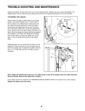
... cables need to slip off the weight stack. If a cable tends to be lifted off the pulleys often, the cable may have become twisted. Replace all cables every two years. 18 Slide the adjustment sleeve and the ball against the indicated 3 1/2" Pulley (15). Pull the end of the Front Upright (42). Remove the cable and re-install it is no slack. TROUBLE-SHOOTING AND MAINTENANCE Inspect and tighten...
... cables need to slip off the weight stack. If a cable tends to be lifted off the pulleys often, the cable may have become twisted. Replace all cables every two years. 18 Slide the adjustment sleeve and the ball against the indicated 3 1/2" Pulley (15). Pull the end of the Front Upright (42). Remove the cable and re-install it is no slack. TROUBLE-SHOOTING AND MAINTENANCE Inspect and tighten...
Uk Manual
Page 19
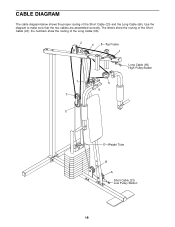
the numbers show the routing of the Short Cable (23); Use the diagram to make sure that the two cables are assembled correctly. CABLE DIAGRAM The cable diagram below shows the proper routing of the Long Cable (66). 2 4 8-Top Frame 1 Long Cable (66) High Pulley Station 7 3 5 6 C D-Weight Tube B A Short Cable (23) Low Pulley Station 19 The letters show the routing of the Short Cable (23) and the Long Cable (66).
the numbers show the routing of the Short Cable (23); Use the diagram to make sure that the two cables are assembled correctly. CABLE DIAGRAM The cable diagram below shows the proper routing of the Long Cable (66). 2 4 8-Top Frame 1 Long Cable (66) High Pulley Station 7 3 5 6 C D-Weight Tube B A Short Cable (23) Low Pulley Station 19 The letters show the routing of the Short Cable (23) and the Long Cable (66).
Uk Manual
Page 20
ORDERING REPLACEMENT PARTS If you , please be prepared to give the following information: • The MODEL NUMBER of the product (WESY60400). • The NAME of the product (WEIDER® VIPER 2000). • The SERIAL NUMBER of the product (see the front cover of this product, contact the ICON Fitness Lifestyle Ltd. Part No. 134042 R0997A WEIDER is a registered trademark of this user's manual). office, or write: ICON Fitness Lifestyle Ltd...
ORDERING REPLACEMENT PARTS If you , please be prepared to give the following information: • The MODEL NUMBER of the product (WESY60400). • The NAME of the product (WEIDER® VIPER 2000). • The SERIAL NUMBER of the product (see the front cover of this product, contact the ICON Fitness Lifestyle Ltd. Part No. 134042 R0997A WEIDER is a registered trademark of this user's manual). office, or write: ICON Fitness Lifestyle Ltd...
Uk Manual
Page 26
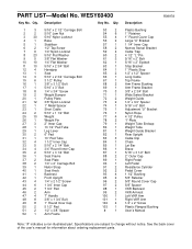
... Wide Swivel Bracket Weight Guide 1/2" x 3/4" Spacer 5/16" x 6" Bolt Adjustment "U" Bracket Nylon Rope 4 1/2" Pulley "I"-Plate Weight Tube Endcap Weight Tube Weight Guide Bracket Rear Upright Cable Clip Chain Lat Bar Brace 5/16" x 3 1/2" Bolt 2" Outer Cap Right Pedal Left Pedal Resistance Cylinder Pedal Cover 1 1/2" Bushing 5/8" Retainer 5/8" Round Cover Cap 5/8" Spacer VKR Backrest VKR Armrest Left VKR Arm Right VKR Arm 1/4" x 2" Screw Plastic Flanged Bushing User's Manual Note: "#" indicates a non-illustrated part. WESY60400 Key No. Specifications are subject to change without notice.
... Wide Swivel Bracket Weight Guide 1/2" x 3/4" Spacer 5/16" x 6" Bolt Adjustment "U" Bracket Nylon Rope 4 1/2" Pulley "I"-Plate Weight Tube Endcap Weight Tube Weight Guide Bracket Rear Upright Cable Clip Chain Lat Bar Brace 5/16" x 3 1/2" Bolt 2" Outer Cap Right Pedal Left Pedal Resistance Cylinder Pedal Cover 1 1/2" Bushing 5/8" Retainer 5/8" Round Cover Cap 5/8" Spacer VKR Backrest VKR Armrest Left VKR Arm Right VKR Arm 1/4" x 2" Screw Plastic Flanged Bushing User's Manual Note: "#" indicates a non-illustrated part. WESY60400 Key No. Specifications are subject to change without notice.


