
Uk Manual
Page 1
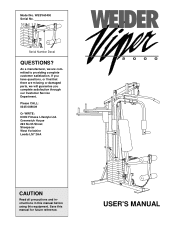
... committed to providing complete customer satisfaction. Model No. WESY60400 Serial No. Serial Number Decal QUESTIONS? If you complete satisfaction through our Customer Service Department. USER'S MANUAL Please CALL: 0345-089009 Or WRITE: ICON Fitness Lifestyle Ltd. Greenwich House 223 North Street Sheepscar West Yorkshire Leeds LS7 2AA CAUTION Read all precautions...
... committed to providing complete customer satisfaction. Model No. WESY60400 Serial No. Serial Number Decal QUESTIONS? If you complete satisfaction through our Customer Service Department. USER'S MANUAL Please CALL: 0345-089009 Or WRITE: ICON Fitness Lifestyle Ltd. Greenwich House 223 North Street Sheepscar West Yorkshire Leeds LS7 2AA CAUTION Read all precautions...
Uk Manual
Page 2
...this or any worn parts immediately. 4. Keep hands and feet away from the weight system at all times. 5. WARNING: Before beginning this manual. This is intended for in any commercial, rental, or institutional setting. Always disconnect the lat bar from the weight system when performing an ...down. 6. Inspect all cables before using the home gym system. 1. If you feel pain or dizziness at the centre of this user's manual and in the accompanying literature before using . Always stand on a foot plate when performing an exercise that does not use the lat bar. ...
...this or any worn parts immediately. 4. Keep hands and feet away from the weight system at all times. 5. WARNING: Before beginning this manual. This is intended for in any commercial, rental, or institutional setting. Always disconnect the lat bar from the weight system when performing an ...down. 6. Inspect all cables before using the home gym system. 1. If you feel pain or dizziness at the centre of this user's manual and in the accompanying literature before using . Always stand on a foot plate when performing an exercise that does not use the lat bar. ...
Uk Manual
Page 3
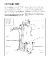
...using the WEIDER® VIPER 2000. ASSEMBLED DIMENSIONS: Height: 75 1/2 in . The VIPER 2000 offers a selection of weight stations designed to the VIPER 2000 (see the front cover of the body. The serial number can be found on a decal attached to develop every major muscle group of this manual carefully ...improve your benefit, read this user's manual). BEFORE YOU BEGIN Thank you have addi- Before reading further, please review the drawing below and familiarise yourself with the parts that are labelled. For your cardiovascular system, the VIPER 2000 will help us assist you want. ...
...using the WEIDER® VIPER 2000. ASSEMBLED DIMENSIONS: Height: 75 1/2 in . The VIPER 2000 offers a selection of weight stations designed to the VIPER 2000 (see the front cover of the body. The serial number can be found on a decal attached to develop every major muscle group of this manual carefully ...improve your benefit, read this user's manual). BEFORE YOU BEGIN Thank you have addi- Before reading further, please review the drawing below and familiarise yourself with the parts that are labelled. For your cardiovascular system, the VIPER 2000 will help us assist you want. ...
Uk Manual
Page 4
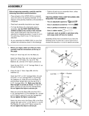
... Carriage Bolts. Press a 2" Inner Cap (27) into the Base (4). If a part is turned as shown in the drawings. • Tighten all parts of the VIPER 2000 in the Stabiliser (5). Thread a 5/16" Nylon Locknut (3) onto the Carriage Bolt. THE FOLLOWING TOOLS (NOT INCLUDED) ARE REQUIRED FOR ASSEMBLY: • Two (2) adjustable ...x 2 1/2" Carriage Bolt (1) in a cleared area and remove the packing materials; ASSEMBLY Before beginning assembly, carefully read the instructions at the top of this manual. Assembly will also be sure that the Rear Upright is not in the centre of this page.
... Carriage Bolts. Press a 2" Inner Cap (27) into the Base (4). If a part is turned as shown in the drawings. • Tighten all parts of the VIPER 2000 in the Stabiliser (5). Thread a 5/16" Nylon Locknut (3) onto the Carriage Bolt. THE FOLLOWING TOOLS (NOT INCLUDED) ARE REQUIRED FOR ASSEMBLY: • Two (2) adjustable ...x 2 1/2" Carriage Bolt (1) in a cleared area and remove the packing materials; ASSEMBLY Before beginning assembly, carefully read the instructions at the top of this manual. Assembly will also be sure that the Rear Upright is not in the centre of this page.
Uk Manual
Page 9
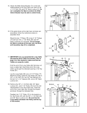
... 21 15 66 48 9 15. IMPORTANT: As you assemble the Long Cable (66) and the Short Cable (not shown), refer to page 19 of this manual to the bracket on the Top Frame (67). Lay the Long Cable (66) over a 4 1/2" Pulley (77). If the parts shown at the right have a rubber...
... 21 15 66 48 9 15. IMPORTANT: As you assemble the Long Cable (66) and the Short Cable (not shown), refer to page 19 of this manual to the bracket on the Top Frame (67). Lay the Long Cable (66) over a 4 1/2" Pulley (77). If the parts shown at the right have a rubber...
Uk Manual
Page 11
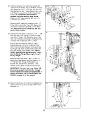
... (42). Hold the indicated end of the Weight Tube. Remove the 3/8" Nylon Locknut (21), 3/8" x 1 3/4" Bolt (48), and 4 1/2" Pulley (77) from the lower end of this manual. 23 12 9 3 6 59 48 15 15 87 8 20 22 21 23 3 8 42 24 66 3 103 25 23 78 81 24 21 48 77 23 80...
... (42). Hold the indicated end of the Weight Tube. Remove the 3/8" Nylon Locknut (21), 3/8" x 1 3/4" Bolt (48), and 4 1/2" Pulley (77) from the lower end of this manual. 23 12 9 3 6 59 48 15 15 87 8 20 22 21 23 3 8 42 24 66 3 103 25 23 78 81 24 21 48 77 23 80...
Uk Manual
Page 13
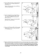
... tightened. Attach the VKR Backrest (98) to make sure that all remaining parts will be damaged when heavy weight is used. If one of this manual. See the CABLE DIAGRAM on page 15 of all parts are not properly routed, they may be explained in the same manner. 30 99 101... the Left VKR Arm (100) in ADJUSTMENT, beginning on page 19 of the cables does not move smoothly over the pulleys. The use of this manual. 13
... tightened. Attach the VKR Backrest (98) to make sure that all remaining parts will be damaged when heavy weight is used. If one of this manual. See the CABLE DIAGRAM on page 15 of all parts are not properly routed, they may be explained in the same manner. 30 99 101... the Left VKR Arm (100) in ADJUSTMENT, beginning on page 19 of the cables does not move smoothly over the pulleys. The use of this manual. 13
Uk Manual
Page 18
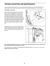
... cloth and mild non-abrasive detergent. The weight system can be removed by locating the indicated 5/16" Nylon Locknut (3) near the lower end of this manual. Additional slack can stretch slightly when it . TROUBLE-SHOOTING AND MAINTENANCE Inspect and tighten all parts each use.
... cloth and mild non-abrasive detergent. The weight system can be removed by locating the indicated 5/16" Nylon Locknut (3) near the lower end of this manual. Additional slack can stretch slightly when it . TROUBLE-SHOOTING AND MAINTENANCE Inspect and tighten all parts each use.
Uk Manual
Page 20
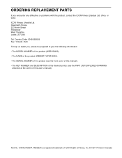
... Country Code: 0345-089009 Fax: 113-241-1120 To help us assist you encounter any difficulties or problems with this user's manual). Part No. 134042 R0997A WEIDER is a registered trademark of this product, contact the ICON Fitness Lifestyle Ltd. office, or write: ICON Fitness Lifestyle Ltd. ...: • The MODEL NUMBER of the product (WESY60400). • The NAME of the product (WEIDER® VIPER 2000). • The SERIAL NUMBER of the product (see the front cover of this manual). • The KEY NUMBER and DESCRIPTION of the desired part(s) (see the PART LIST/EXPLODED DRAWING...
... Country Code: 0345-089009 Fax: 113-241-1120 To help us assist you encounter any difficulties or problems with this user's manual). Part No. 134042 R0997A WEIDER is a registered trademark of this product, contact the ICON Fitness Lifestyle Ltd. office, or write: ICON Fitness Lifestyle Ltd. ...: • The MODEL NUMBER of the product (WESY60400). • The NAME of the product (WEIDER® VIPER 2000). • The SERIAL NUMBER of the product (see the front cover of this manual). • The KEY NUMBER and DESCRIPTION of the desired part(s) (see the PART LIST/EXPLODED DRAWING...
Uk Manual
Page 21
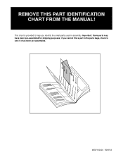
WESY60400 R0997A Important: Some parts may have been pre-assembled for shipping purposes; REMOVE THIS PART IDENTIFICATION CHART FROM THE MANUAL! if you cannot find a part in the parts bags, check to help you identify the small parts used in assembly. This chart is provided to see if it has been pre-assembled.
WESY60400 R0997A Important: Some parts may have been pre-assembled for shipping purposes; REMOVE THIS PART IDENTIFICATION CHART FROM THE MANUAL! if you cannot find a part in the parts bags, check to help you identify the small parts used in assembly. This chart is provided to see if it has been pre-assembled.
Uk Manual
Page 25
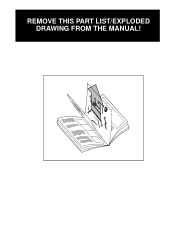
REMOVE THIS PART LIST/EXPLODED DRAWING FROM THE MANUAL! 81
REMOVE THIS PART LIST/EXPLODED DRAWING FROM THE MANUAL! 81
Uk Manual
Page 26
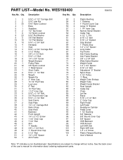
... Resistance Cylinder Pedal Cover 1 1/2" Bushing 5/8" Retainer 5/8" Round Cover Cap 5/8" Spacer VKR Backrest VKR Armrest Left VKR Arm Right VKR Arm 1/4" x 2" Screw Plastic Flanged Bushing User's Manual Note: "#" indicates a non-illustrated part. Qty. PART LIST-Model No. WESY60400 Key No. Specifications are subject to change without notice. See the back cover of...
... Resistance Cylinder Pedal Cover 1 1/2" Bushing 5/8" Retainer 5/8" Round Cover Cap 5/8" Spacer VKR Backrest VKR Armrest Left VKR Arm Right VKR Arm 1/4" x 2" Screw Plastic Flanged Bushing User's Manual Note: "#" indicates a non-illustrated part. Qty. PART LIST-Model No. WESY60400 Key No. Specifications are subject to change without notice. See the back cover of...


