
English Manual
Page 1
... UNNECESSARY DELAYS, PLEASE CALL DIRECT TO OUR TOLL-FREE CUSTOMER HOT LINE. The trained technicians on our customer hot line will guarantee complete satisfaction through direct assistance from our factory. Write the serial number in the location shown below. MST CAUTION Read all precautions and instructions in this manual before using this manual for future reference. ¨ Model No. Save this equipment...
... UNNECESSARY DELAYS, PLEASE CALL DIRECT TO OUR TOLL-FREE CUSTOMER HOT LINE. The trained technicians on our customer hot line will guarantee complete satisfaction through direct assistance from our factory. Write the serial number in the location shown below. MST CAUTION Read all precautions and instructions in this manual before using this manual for future reference. ¨ Model No. Save this equipment...
English Manual
Page 2
... setting. Remove the PART LIST/EXPLODED DRAWING and the PART IDENTIFICATION CHART before using . Always wear athletic shoes for protection. 11. ICON assumes no responsibility for home use the home gym in the accompanying literature before using the home gym. 1. Use the home gym only on the pulleys at all parts often. Replace any time while exercising, stop immediately and make sure the cables are raised. Never release the press arms, butterfly arms, leg lever, lat bar or ab strap while weights...
... setting. Remove the PART LIST/EXPLODED DRAWING and the PART IDENTIFICATION CHART before using . Always wear athletic shoes for protection. 11. ICON assumes no responsibility for home use the home gym in the accompanying literature before using the home gym. 1. Use the home gym only on the pulleys at all parts often. Replace any time while exercising, stop immediately and make sure the cables are raised. Never release the press arms, butterfly arms, leg lever, lat bar or ab strap while weights...
English Manual
Page 3
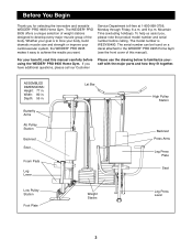
... Leg Lever Lat Bar High Pulley Station Backrest Press Arms Leg Press Plate Seat Low Pulley Station Foot Plate Weight Stacks Leg Press Lever 3 Whether your goal is WESY99490. Depth: 55 in. The model number is to tone your body, build dramatic muscle size and strength or improve your benefit, read this manual). For your cardiovascular system, the WEIDER¨ PRO 9935 makes it easy to the WEIDER¨ PRO 9935 Home Gym (see the front cover...
... Leg Lever Lat Bar High Pulley Station Backrest Press Arms Leg Press Plate Seat Low Pulley Station Foot Plate Weight Stacks Leg Press Lever 3 Whether your goal is WESY99490. Depth: 55 in. The model number is to tone your body, build dramatic muscle size and strength or improve your benefit, read this manual). For your cardiovascular system, the WEIDER¨ PRO 9935 makes it easy to the WEIDER¨ PRO 9935 Home Gym (see the front cover...
English Manual
Page 4
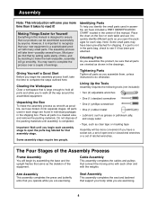
.... All parts used in a cleared area and remove the packing materials. Cable Assembly This assembly completes the cables and pulleys that assembly stage. Giving Yourself a Good Start Before you open the packages for that connect the moving arms with many small parts. Clearing the Workspace Clear a workspace that serve as you begin by assembling the base and the upright frames that is a sophisticated product with each step. Unpacking...
.... All parts used in a cleared area and remove the packing materials. Cable Assembly This assembly completes the cables and pulleys that assembly stage. Giving Yourself a Good Start Before you open the packages for that connect the moving arms with many small parts. Clearing the Workspace Clear a workspace that serve as you begin by assembling the base and the upright frames that is a sophisticated product with each step. Unpacking...
English Manual
Page 5
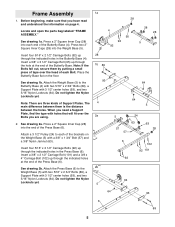
... the indicated holes in the Press Base (6). Do not tighten the Nylon Locknuts yet. Attach a 3 1/2Ó Pulley (24) to each of the Butterfly Base (4). Attach the Press Base (6) to the Butterfly Base (4) with two 5/16Ó x 2 3/4Ó Bolts (89), a Support Plate with 3 1/2Ó center holes (93), and two 5/16Ó Nylon Locknuts (64). Frame Assembly 1. Press a 2Ó Square Inner Cap...
... the indicated holes in the Press Base (6). Do not tighten the Nylon Locknuts yet. Attach a 3 1/2Ó Pulley (24) to each of the Butterfly Base (4). Attach the Press Base (6) to the Butterfly Base (4) with two 5/16Ó x 2 3/4Ó Bolts (89), a Support Plate with 3 1/2Ó center holes (93), and two 5/16Ó Nylon Locknuts (64). Frame Assembly 1. Press a 2Ó Square Inner Cap...

English Manual
Page 7
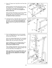
... the Press Upright (2). Hand tighten a 3/8Ó Nylon Jamnut (63) onto the 3/8Ó x 2 1/2Ó Carriage Bolt (101). Press a 2Ó Square Inner Cap (28) into the small tube 7 on the lower end of the Support Frame (3) over the indicated 5/16Ó x 2 1/2Ó Carriage Bolts (92) in the Press Base (6). Attach the Support Frame (3) to the indicated bracket at the top of the Front Leg...
... the Press Upright (2). Hand tighten a 3/8Ó Nylon Jamnut (63) onto the 3/8Ó x 2 1/2Ó Carriage Bolt (101). Press a 2Ó Square Inner Cap (28) into the small tube 7 on the lower end of the Support Frame (3) over the indicated 5/16Ó x 2 1/2Ó Carriage Bolts (92) in the Press Base (6). Attach the Support Frame (3) to the indicated bracket at the top of the Front Leg...
English Manual
Page 8
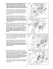
... the lower end of the holes. Do not tighten the Nylon Locknuts yet. 64 Attach the Press Seat Frame (7) to the Weight Base (5) with the Bolt and a 3/8Ó Nylon Locknut (50). 9. Slide the bracket on the Weight Tube (17). 11 15 16 Groove Pin 17 21 Pin Grooves 5 48 46 8 6 Lubricate 88 18 51 48 50 Lubricate the 3/8Ó x 3Ó Bolt (88). Slide a Weight Guide...
... the lower end of the holes. Do not tighten the Nylon Locknuts yet. 64 Attach the Press Seat Frame (7) to the Weight Base (5) with the Bolt and a 3/8Ó Nylon Locknut (50). 9. Slide the bracket on the Weight Tube (17). 11 15 16 Groove Pin 17 21 Pin Grooves 5 48 46 8 6 Lubricate 88 18 51 48 50 Lubricate the 3/8Ó x 3Ó Bolt (88). Slide a Weight Guide...
English Manual
Page 9
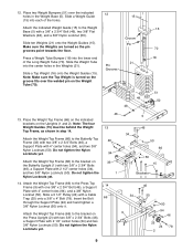
...50). Attach the Weight Top Frame (66) to the Butterfly Top Frame (33) with two 3/8Ó x 2 3/4Ó Bolts (46), a Support Plate with 2 1/2Ó center holes (34), and two 3/8Ó Nylon Locknuts (50). Slide a Top Weight (16) onto the Weight Guides (15). Slide a 3 1/2Ó Pulley (...Weight Bumpers (51) over the welded pin on the Press Upright (2) with two 3/8Ó x 2 3/4Ó Bolts (46), a Support Plate with a Cable Trap (25) onto a 3/8Ó x 4Ó Bolt (78). Note: Make sure the Top Weight is turned so the groove fits over the indicated 12 holes in step 14. Do not tighten...
...50). Attach the Weight Top Frame (66) to the Butterfly Top Frame (33) with two 3/8Ó x 2 3/4Ó Bolts (46), a Support Plate with 2 1/2Ó center holes (34), and two 3/8Ó Nylon Locknuts (50). Slide a Top Weight (16) onto the Weight Guides (15). Slide a 3 1/2Ó Pulley (...Weight Bumpers (51) over the welded pin on the Press Upright (2) with two 3/8Ó x 2 3/4Ó Bolts (46), a Support Plate with a Cable Trap (25) onto a 3/8Ó x 4Ó Bolt (78). Note: Make sure the Top Weight is turned so the groove fits over the indicated 12 holes in step 14. Do not tighten...
English Manual
Page 10
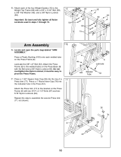
... to assemble the second Press Arm (77, not shown). 8 8 50 6 Lubricate 100 Welded Tube 52 35 76 64 87 77 10 Attach the Press Arm (77) to the bracket on the Press Frame (8). 15. Attach the Press Frame (8) to the Weight Top Frame (66) with the Bolt and a 3/8Ó Nylon Locknut (50). Important: Go back and fully tighten all Nylon Locknuts used in the Press Arm. Press...
... to assemble the second Press Arm (77, not shown). 8 8 50 6 Lubricate 100 Welded Tube 52 35 76 64 87 77 10 Attach the Press Arm (77) to the bracket on the Press Frame (8). 15. Attach the Press Frame (8) to the Weight Top Frame (66) with the Bolt and a 3/8Ó Nylon Locknut (50). Important: Go back and fully tighten all Nylon Locknuts used in the Press Arm. Press...
English Manual
Page 11
... routing during steps 19 to 49, refer to assemble the Left Butterfly Arm (10, not shown). 18 11 35 33 Axle 35 31 38 29 Cable Assembly 19. Lubricate the indicated axle on the Cable and the two Nylon Jamnuts must be mounted underneath the welded bracket. 20. Locate and open the parts bag labeled ÒCABLE 19 ASSEMBLY AND PULLEYS.Ó For Cable identifica- Attach...
... routing during steps 19 to 49, refer to assemble the Left Butterfly Arm (10, not shown). 18 11 35 33 Axle 35 31 38 29 Cable Assembly 19. Lubricate the indicated axle on the Cable and the two Nylon Jamnuts must be mounted underneath the welded bracket. 20. Locate and open the parts bag labeled ÒCABLE 19 ASSEMBLY AND PULLEYS.Ó For Cable identifica- Attach...
English Manual
Page 12
... Arm (11) with a 3/8Ó x 1 3/4Ó Bolt (57) and a 3/8Ó Nylon Locknut (50). Attach the Pulley and Pulley Covers to the bracket on the Upright. 47 Pin 74 24 63 48 1 12 21. Wrap the Butterfly Cable (73) around a ÒVÓ-Pulley (27) in the Butterfly Upright (1) with a 3/8Ó x 2 1/2Ó Bolt (53) and a 3/8Ó Nylon Locknut (50). Attach the Butterfly Cable (73) to the Small Pulley...
... Arm (11) with a 3/8Ó x 1 3/4Ó Bolt (57) and a 3/8Ó Nylon Locknut (50). Attach the Pulley and Pulley Covers to the bracket on the Upright. 47 Pin 74 24 63 48 1 12 21. Wrap the Butterfly Cable (73) around a ÒVÓ-Pulley (27) in the Butterfly Upright (1) with a 3/8Ó x 2 1/2Ó Bolt (53) and a 3/8Ó Nylon Locknut (50). Attach the Butterfly Cable (73) to the Small Pulley...

English Manual
Page 15
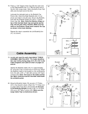
... 63 Remove the pre-attached Pro Pulley (26) from the 34 3/8Ó x 4 3/4Ó Bolt (60) inserted into the Butterfly Upright (1) in the direction shown. Attach the Pro Pulley and a Cable Trap (25) to the bracket on the Butterfly Base (4). Wrap the Low Pulley Cable (75) around a 3 1/2Ó 32 Pulley (24) in step 32. Route the Low Pulley Cable (75) under a Pro Pulley (26) as shown. 31. Identify the Low Pulley Cable (75...
... 63 Remove the pre-attached Pro Pulley (26) from the 34 3/8Ó x 4 3/4Ó Bolt (60) inserted into the Butterfly Upright (1) in the direction shown. Attach the Pro Pulley and a Cable Trap (25) to the bracket on the Butterfly Base (4). Wrap the Low Pulley Cable (75) around a 3 1/2Ó 32 Pulley (24) in step 32. Route the Low Pulley Cable (75) under a Pro Pulley (26) as shown. 31. Identify the Low Pulley Cable (75...
English Manual
Page 17
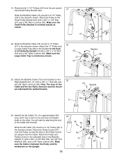
... 63 17 Route the Press Cable (72) back through the opening in the direction shown. Wrap the Press Cable (72) around a 3 1/2Ó Pulley 42 (24) in the Press Frame (8) with a 3/8Ó x 4 3/4Ó Bolt (60) and a 3/8Ó Nylon Jamnut (63). Attach the ÒVÓ-Pulley and a Large Cable Trap (32) to the small tube on the inside of the home gym. Make sure the Cable Trap is...
... 63 17 Route the Press Cable (72) back through the opening in the direction shown. Wrap the Press Cable (72) around a 3 1/2Ó Pulley 42 (24) in the Press Frame (8) with a 3/8Ó x 4 3/4Ó Bolt (60) and a 3/8Ó Nylon Jamnut (63). Attach the ÒVÓ-Pulley and a Large Cable Trap (32) to the small tube on the inside of the home gym. Make sure the Cable Trap is...
English Manual
Page 18
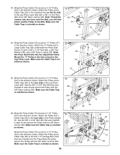
... two turns onto the Bolt; you will later attach another Pulley to the Leg Press Lever. Attach the ÒVÓ-Pulley and a Large Cable Trap (32) underneath the Press Seat Frame (7) with the 3/8Ó Nylon 2 Jamnut (63). Wrap the Press Cable (72) around a 3 1/2Ó Pulley (24) in the direction shown. Attach the Pulley and a Cable Trap (25) to the 3/8Ó x 4Ó Carriage Bolt (102) that was inserted in step 43...
... two turns onto the Bolt; you will later attach another Pulley to the Leg Press Lever. Attach the ÒVÓ-Pulley and a Large Cable Trap (32) underneath the Press Seat Frame (7) with the 3/8Ó Nylon 2 Jamnut (63). Wrap the Press Cable (72) around a 3 1/2Ó Pulley (24) in the direction shown. Attach the Pulley and a Cable Trap (25) to the 3/8Ó x 4Ó Carriage Bolt (102) that was inserted in step 43...
English Manual
Page 22
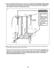
... of this manual to remove the slack by tightening the cables. 55. Make sure that the cables move smoothly, find and correct the problem. Before using the home gym, pull each cable a few times to make sure that all parts have been attached to the home gym in the locations shown. Apply the WEIDER PRO 9935 decal in the appropriate location. 55 WEIDER PRO 9935 56. IMPORTANT: If the cables are not properly installed, they...
... of this manual to remove the slack by tightening the cables. 55. Make sure that the cables move smoothly, find and correct the problem. Before using the home gym, pull each cable a few times to make sure that all parts have been attached to the home gym in the locations shown. Apply the WEIDER PRO 9935 decal in the appropriate location. 55 WEIDER PRO 9935 56. IMPORTANT: If the cables are not properly installed, they...
English Manual
Page 25
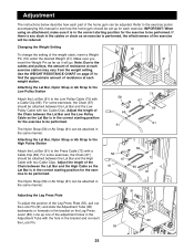
Use the WEIGHT RESISTANCE CHART on the Leg Press Lever (83). Adjust the length of the Chain between the Lat Bar and the Low Pulley Cable with two Cable Clips. Note: Due to the cables and pulleys, the amount of resistance at each exercise station may vary from the weight setting. Attaching the Lat Bar, Nylon Strap or Ab Strap to the Low Pulley Station Attach the Lat Bar (61) to the Low Pulley Cable (75) with a Cable Clip (69). Line...
Use the WEIGHT RESISTANCE CHART on the Leg Press Lever (83). Adjust the length of the Chain between the Lat Bar and the Low Pulley Cable with two Cable Clips. Note: Due to the cables and pulleys, the amount of resistance at each exercise station may vary from the weight setting. Attaching the Lat Bar, Nylon Strap or Ab Strap to the Low Pulley Station Attach the Lat Bar (61) to the Low Pulley Cable (75) with a Cable Clip (69). Line...
English Manual
Page 26
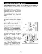
...;-Pulley (27) is attached to a different set of adjustment holes. ing one or both pulleys (24) to the Press Seat Frame (7). Do not use the home gym. By moving the ÒVÓ-Pulley closer to any worn parts immediately. Re-attach the Pulley and Cable Trap to tighten the cables. There are three free holes in the small tube, and you can be removed form the Press Cable (72) by moving one more, as needed , move...
...;-Pulley (27) is attached to a different set of adjustment holes. ing one or both pulleys (24) to the Press Seat Frame (7). Do not use the home gym. By moving the ÒVÓ-Pulley closer to any worn parts immediately. Re-attach the Pulley and Cable Trap to tighten the cables. There are three free holes in the small tube, and you can be removed form the Press Cable (72) by moving one more, as needed , move...

English Manual
Page 27
... be tightened by tightening the Ab Cable (74) as described above or by removing the 5/16Ó x 1 3/4Ó Bolt (96) and the 5/16Ó Nylon Locknut (64). The Press Cable (72) is the only cable attached to differences in individual weight plates as well as described on the previous page. 74 64 97 72 96 71 68 17 Weight Resistance Chart The chart below...
... be tightened by tightening the Ab Cable (74) as described above or by removing the 5/16Ó x 1 3/4Ó Bolt (96) and the 5/16Ó Nylon Locknut (64). The Press Cable (72) is the only cable attached to differences in individual weight plates as well as described on the previous page. 74 64 97 72 96 71 68 17 Weight Resistance Chart The chart below...
English Manual
Page 31
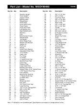
...; Bolt 3/8Ó x 2Ó Bolt Leg Press Plate 3/8Ó x 3 1/2Ó Bolt 3/8Ó x 1 3/4Ó Bolt Nylon Strap 3/8Ó x 3 3/4Ó Bolt 3/8Ó x 4 3/4Ó Bolt Lat Bar 3/8Ó x 3 1/4Ó Bolt 3/8Ó Nylon Jamnut 5/16Ó Nylon Locknut Seat Plate Weight Top Frame Chain 1/4Ó Nylon Locknut Cable Clip Long Weight Tube 1/4Ó Flat Washer Press Cable Butterfly Cable Ab Cable Low Pulley Cable 1Ó Round Inner Cap Press Arm 3/8Ó x 4Ó Bolt 1/4Ó x 2 1/2Ó Bolt 1Ó Tap Screw Ab Strap 4 1/2Ó Pulley Leg Press Lever...
...; Bolt 3/8Ó x 2Ó Bolt Leg Press Plate 3/8Ó x 3 1/2Ó Bolt 3/8Ó x 1 3/4Ó Bolt Nylon Strap 3/8Ó x 3 3/4Ó Bolt 3/8Ó x 4 3/4Ó Bolt Lat Bar 3/8Ó x 3 1/4Ó Bolt 3/8Ó Nylon Jamnut 5/16Ó Nylon Locknut Seat Plate Weight Top Frame Chain 1/4Ó Nylon Locknut Cable Clip Long Weight Tube 1/4Ó Flat Washer Press Cable Butterfly Cable Ab Cable Low Pulley Cable 1Ó Round Inner Cap Press Arm 3/8Ó x 4Ó Bolt 1/4Ó x 2 1/2Ó Bolt 1Ó Tap Screw Ab Strap 4 1/2Ó Pulley Leg Press Lever...
English Manual
Page 33
... by ICON. Accordingly, the above limitation may not apply to replacing or repairing, at ICON's option, the product at the center of the product (WEIDER¨ PRO 9935 Home Gym System) 3. until 6 p.m. Some states do not allow the exclusion or limitation of merchantability or fitness for commercial or rental purposes, or products used as store display models. The warranty extended hereunder is limited in connection with the use or...
... by ICON. Accordingly, the above limitation may not apply to replacing or repairing, at ICON's option, the product at the center of the product (WEIDER¨ PRO 9935 Home Gym System) 3. until 6 p.m. Some states do not allow the exclusion or limitation of merchantability or fitness for commercial or rental purposes, or products used as store display models. The warranty extended hereunder is limited in connection with the use or...


