
English Manual
Page 2
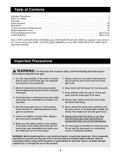
...gym for foot protection when exercising. 4. The weights will fall with pre-existing health problems. Read all instructions before beginning assembly. Do not use of this or any exercise program, consult your physician. Important Precautions WARNING: To reduce the risk of... DRAWING and the PART IDENTIFICATION CHART before using the home gym. 1. Table of Contents Important Precautions 2 Before You Begin 3 Assembly 4 Cable Diagrams 23 Adjustment 25 Trouble-shooting and Maintenance 26 Weight Resistance Chart 27 Ordering Replacement Parts Back Cover Limited Warranty Back...
...gym for foot protection when exercising. 4. The weights will fall with pre-existing health problems. Read all instructions before beginning assembly. Do not use of this or any exercise program, consult your physician. Important Precautions WARNING: To reduce the risk of... DRAWING and the PART IDENTIFICATION CHART before using the home gym. 1. Table of Contents Important Precautions 2 Before You Begin 3 Assembly 4 Cable Diagrams 23 Adjustment 25 Trouble-shooting and Maintenance 26 Weight Resistance Chart 27 Ordering Replacement Parts Back Cover Limited Warranty Back...
English Manual
Page 3
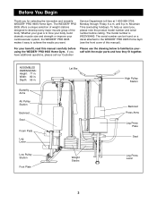
... Lever 3 Service Department toll-free at 1-800-999-3756, Monday through Friday, 6 a.m. Width: 80 in . The WEIDER¨ PRO 9935 offers a unique selection of weight stations designed to develop every major muscle group of this manual carefully before calling. The serial...your cardiovascular system, the WEIDER¨ PRO 9935 makes it easy to achieve the results you , please note the product model number and serial number before using the WEIDER¨ PRO 9935 Home Gym. If you for selecting the innovative and versatile WEIDER¨ PRO 9935 Home Gym. ASSEMBLED DIMENSIONS: Height: 77 ...
... Lever 3 Service Department toll-free at 1-800-999-3756, Monday through Friday, 6 a.m. Width: 80 in . The WEIDER¨ PRO 9935 offers a unique selection of weight stations designed to develop every major muscle group of this manual carefully before calling. The serial...your cardiovascular system, the WEIDER¨ PRO 9935 makes it easy to achieve the results you , please note the product model number and serial number before using the WEIDER¨ PRO 9935 Home Gym. If you for selecting the innovative and versatile WEIDER¨ PRO 9935 Home Gym. ASSEMBLED DIMENSIONS: Height: 77 ...
English Manual
Page 4
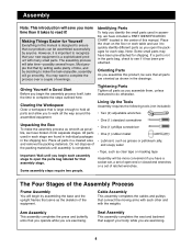
.... Place the chart on the floor or work table and use it ! Note: Some small parts may want to do otherwise. Lining Up the Tools Assembly requires the following tools (not included): ¥ Two (2) adjustable wrenches ¥ One (1) standard screwdriver ¥ One (1) phillips screwdriver ¥ One ... bag labeled for each stage are exercising. 4 Giving Yourself a Good Start Before you are oriented as the skeleton of the Assembly Process Frame Assembly You will take the time to open the packages for that all parts in the shipping box. Clearing the Workspace Clear a ...
.... Place the chart on the floor or work table and use it ! Note: Some small parts may want to do otherwise. Lining Up the Tools Assembly requires the following tools (not included): ¥ Two (2) adjustable wrenches ¥ One (1) standard screwdriver ¥ One (1) phillips screwdriver ¥ One ... bag labeled for each stage are exercising. 4 Giving Yourself a Good Start Before you are oriented as the skeleton of the Assembly Process Frame Assembly You will take the time to open the packages for that all parts in the shipping box. Clearing the Workspace Clear a ...
English Manual
Page 5
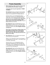
...with two 5/16Ó x 2 3/4Ó Bolts (89), a Support Plate with a 3/8Ó x 1 3/4Ó Bolt (57) and a 3/8Ó Nylon Jamnut (63). Frame Assembly 1. Attach the Weight Base (5) to the Weight Base (5) with two 5/16Ó x 2 3/4Ó Bolts (89), a Support Plate with holes that you have read and understood... There are using. 2. Do not tighten the Nylon Locknuts yet. See drawing 2a. Locate and open the parts bag labeled ÒFRAME ASSEMBLY.Ó See drawing 1a. The main difference between them by putting a small piece of the Butterfly Base. Note: If the Bolts fall ...
...with two 5/16Ó x 2 3/4Ó Bolts (89), a Support Plate with a 3/8Ó x 1 3/4Ó Bolt (57) and a 3/8Ó Nylon Jamnut (63). Frame Assembly 1. Attach the Weight Base (5) to the Weight Base (5) with two 5/16Ó x 2 3/4Ó Bolts (89), a Support Plate with holes that you have read and understood... There are using. 2. Do not tighten the Nylon Locknuts yet. See drawing 2a. Locate and open the parts bag labeled ÒFRAME ASSEMBLY.Ó See drawing 1a. The main difference between them by putting a small piece of the Butterfly Base. Note: If the Bolts fall ...
English Manual
Page 10
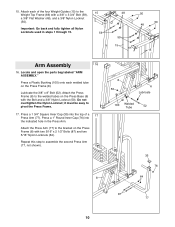
... Frame (8). Press a 1 3/4Ó Square Inner Cap (35) into the indicated hole in steps 1 through 15. 15 59 48 59 15 50 50 48 15 Arm Assembly 16 16. Attach the Press Arm (77) to the bracket on the Press Base (6) with the Bolt and a 3/8Ó Nylon Locknut (50). Important: Go back... and fully tighten all Nylon Locknuts used in the Press Arm. Do not overtighten the Nylon Locknut; it must be easy to assemble the second Press Arm (77, not shown). 8 8 50 6 Lubricate 100 Welded Tube 52 35 76 64 87 77 10 Press a 1Ó Round Inner Cap (76...
... Frame (8). Press a 1 3/4Ó Square Inner Cap (35) into the indicated hole in steps 1 through 15. 15 59 48 59 15 50 50 48 15 Arm Assembly 16 16. Attach the Press Arm (77) to the bracket on the Press Base (6) with the Bolt and a 3/8Ó Nylon Locknut (50). Important: Go back... and fully tighten all Nylon Locknuts used in the Press Arm. Do not overtighten the Nylon Locknut; it must be easy to assemble the second Press Arm (77, not shown). 8 8 50 6 Lubricate 100 Welded Tube 52 35 76 64 87 77 10 Press a 1Ó Round Inner Cap (76...
English Manual
Page 11
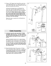
...(84) and two 3/8Ó Nylon Jamnuts (63). Identify the Butterfly Cable (73). Attach the Butterfly Cable to assemble the Left Butterfly Arm (10, not shown). 18 11 35 33 Axle 35 31 38 29 Cable Assembly 19. Wrap the Butterfly Cable (73) around a ÒVÓ-Pulley 20 (27) in the inset drawing...a hammer. Note: Place the Retainer Rings on the Left Butterfly Arm (10) with soapy water. Locate and open the parts bag labeled ÒCABLE 19 ASSEMBLY AND PULLEYS.Ó For Cable identifica- Wet the lower end of the inverted Outer Cap and gently tap the Cap onto the axle with two...
...(84) and two 3/8Ó Nylon Jamnuts (63). Identify the Butterfly Cable (73). Attach the Butterfly Cable to assemble the Left Butterfly Arm (10, not shown). 18 11 35 33 Axle 35 31 38 29 Cable Assembly 19. Wrap the Butterfly Cable (73) around a ÒVÓ-Pulley 20 (27) in the inset drawing...a hammer. Note: Place the Retainer Rings on the Left Butterfly Arm (10) with soapy water. Locate and open the parts bag labeled ÒCABLE 19 ASSEMBLY AND PULLEYS.Ó For Cable identifica- Wet the lower end of the inverted Outer Cap and gently tap the Cap onto the axle with two...
English Manual
Page 13
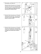
...) and a 3/8Ó Nylon Locknut (50). Make sure the Cable Trap is oriented as shown. 25 54 26. Remove both 3 1/2Ó Pulleys (24) from the pre-assembled Adjustable Pulley Plates (23). 25.
...) and a 3/8Ó Nylon Locknut (50). Make sure the Cable Trap is oriented as shown. 25 54 26. Remove both 3 1/2Ó Pulleys (24) from the pre-assembled Adjustable Pulley Plates (23). 25.
English Manual
Page 20
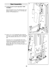
... 1/4Ó x 3/4Ó Bolts (49). Attach the Seat Plate to the indicated holes in a Seat Plate (65). Locate and open the parts bag labeled ÒSEAT ASSEMBLY.Ó Attach the Backrest (12) to the Press Backrest (99) with a 1/4Ó Flat Washer (71) and a 1/4Ó Nylon Locknut (68). Insert a 1/4Ó x 2 1/2Ó Carriage Bolt... other end of the Press Backrest (99) with two 1/4Ó x 2 1/2Ó Bolts (79) and two 1/4Ó Flat Washers (71). 12 1 79 71 79 51. Seat Assembly 50 50.
... 1/4Ó x 3/4Ó Bolts (49). Attach the Seat Plate to the indicated holes in a Seat Plate (65). Locate and open the parts bag labeled ÒSEAT ASSEMBLY.Ó Attach the Backrest (12) to the Press Backrest (99) with a 1/4Ó Flat Washer (71) and a 1/4Ó Nylon Locknut (68). Insert a 1/4Ó x 2 1/2Ó Carriage Bolt... other end of the Press Backrest (99) with two 1/4Ó x 2 1/2Ó Bolts (79) and two 1/4Ó Flat Washers (71). 12 1 79 71 79 51. Seat Assembly 50 50.
English Manual
Page 21
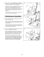
... (49). Insert one Pad Tube (42) into the indicated hole in the same manner. 52 13 45 65 14 49 71 68 71 79 Miscellaneous Assembly 53. Note: The lip on the Leg Press Plate must be on the back of the Seat (13) with a 5/16Ó x 2 1/2Ó Bolt (87), two...
... (49). Insert one Pad Tube (42) into the indicated hole in the same manner. 52 13 45 65 14 49 71 68 71 79 Miscellaneous Assembly 53. Note: The lip on the Leg Press Plate must be on the back of the Seat (13) with a 5/16Ó x 2 1/2Ó Bolt (87), two...


