
English Manual
Page 1
¨ Model No. Serial Number Decal QUESTIONS? As a manufacturer, we are committed to you have questions, or if there are missing parts, we will provide immediate assistance, free of charge to providing complete customer satisfaction. TO AVOID UNNECESSARY DELAYS, PLEASE CALL DIRECT TO OUR TOLL-FREE CUSTOMER HOT LINE. CUSTOMER HOT LINE: 1-800-999-3756 Mon.ÐFri., 6 a.m.Ð6 p.m. MST CAUTION Read all precautions and instructions in the space above. Write the serial number in this manual before using this manual for future reference. WESY99490 Serial No. If ...
¨ Model No. Serial Number Decal QUESTIONS? As a manufacturer, we are committed to you have questions, or if there are missing parts, we will provide immediate assistance, free of charge to providing complete customer satisfaction. TO AVOID UNNECESSARY DELAYS, PLEASE CALL DIRECT TO OUR TOLL-FREE CUSTOMER HOT LINE. CUSTOMER HOT LINE: 1-800-999-3756 Mon.ÐFri., 6 a.m.Ð6 p.m. MST CAUTION Read all precautions and instructions in the space above. Write the serial number in this manual before using this manual for future reference. WESY99490 Serial No. If ...
English Manual
Page 2
If you are exercising, stop immediately and begin cooling down. 8. Use the home gym only on the pulleys at all times. 10. The weights will fall with pre-existing health problems. Read all times. WARNING: Before beginning this manual. tions before using. Always wear athletic shoes for protection. 11. Keep children under the age of 12 and pets away from the home gym at all instructions before using the home gym. 3. Inspect and tighten all of the pulleys. 12. ICON assumes no responsibility for personal injury or property damage sustained by or through the use ...
If you are exercising, stop immediately and begin cooling down. 8. Use the home gym only on the pulleys at all times. 10. The weights will fall with pre-existing health problems. Read all times. WARNING: Before beginning this manual. tions before using. Always wear athletic shoes for protection. 11. Keep children under the age of 12 and pets away from the home gym at all instructions before using the home gym. 3. Inspect and tighten all of the pulleys. 12. ICON assumes no responsibility for personal injury or property damage sustained by or through the use ...
English Manual
Page 3
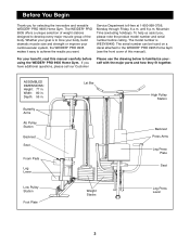
...Leg Press Lever 3 Mountain Time (excluding holidays). If you want. ASSEMBLED DIMENSIONS: Height: 77 in . For your cardiovascular system, the WEIDER¨ PRO 9935 makes it easy to tone your body, build dramatic muscle size and strength or improve your benefit, read this manual). Depth: 55 in.... To help us assist you for selecting the innovative and versatile WEIDER¨ PRO 9935 Home Gym. until 6 p.m. Whether your goal is WESY99490. Before You Begin Thank you , please note the product model number and...
...Leg Press Lever 3 Mountain Time (excluding holidays). If you want. ASSEMBLED DIMENSIONS: Height: 77 in . For your cardiovascular system, the WEIDER¨ PRO 9935 makes it easy to tone your body, build dramatic muscle size and strength or improve your benefit, read this manual). Depth: 55 in.... To help us assist you for selecting the innovative and versatile WEIDER¨ PRO 9935 Home Gym. until 6 p.m. Whether your goal is WESY99490. Before You Begin Thank you , please note the product model number and...
English Manual
Page 4
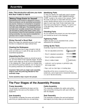
Most people find that is a sophisticated product with the weights. Note: Some small parts may want to complete the process over a couple of time, and by deciding to make the assembly process as smooth as clear tape or masking tape Assembly will take the time to walk all the way around the assembled equipment. Giving Yourself a Good Start Before you open the packages for Yourself Everything in assembly, we have a socket set, a set of the Assembly Process Frame Assembly You will begin the assembly process itself, take timeÑpossibly several hours. Clearing the ...
Most people find that is a sophisticated product with the weights. Note: Some small parts may want to complete the process over a couple of time, and by deciding to make the assembly process as smooth as clear tape or masking tape Assembly will take the time to walk all the way around the assembled equipment. Giving Yourself a Good Start Before you open the packages for Yourself Everything in assembly, we have a socket set, a set of the Assembly Process Frame Assembly You will begin the assembly process itself, take timeÑpossibly several hours. Clearing the ...
English Manual
Page 5
See drawing 1b. Attach the Press Base (6) to each of the Butterfly Base (4). Locate and open the parts bag labeled ÒFRAME ASSEMBLY.Ó See drawing 1a. Press two 2Ó Square Inner Caps (28) into the end of Support Plates. Note: If the Bolts fall out, secure them is the distance between the holes. See drawing 2b. Do not tighten the Nylon Locknuts yet. See drawing 2a. Do not tighten the Nylon Locknuts yet. 1a 28 4 95 92 92 28 28 5 28 1b 89 93 64 64 4 5 2a 5 24 63 57 57 63 28 6 92 102 92 101 2b 64 5 64 93 6 89 5 Press a 2Ó Square ...
See drawing 1b. Attach the Press Base (6) to each of the Butterfly Base (4). Locate and open the parts bag labeled ÒFRAME ASSEMBLY.Ó See drawing 1a. Press two 2Ó Square Inner Caps (28) into the end of Support Plates. Note: If the Bolts fall out, secure them is the distance between the holes. See drawing 2b. Do not tighten the Nylon Locknuts yet. See drawing 2a. Do not tighten the Nylon Locknuts yet. 1a 28 4 95 92 92 28 28 5 28 1b 89 93 64 64 4 5 2a 5 24 63 57 57 63 28 6 92 102 92 101 2b 64 5 64 93 6 89 5 Press a 2Ó Square ...
English Manual
Page 6
Hand tighten two 5/16Ó Nylon Locknuts (64) onto the Bolts. Do not tighten the Nylon Locknuts yet. 1 64 4 92 4. Attach the Butterfly Seat Frame (14) to the Butterfly Upright (1) with two 5/16Ó x 2 3/4Ó Bolts (89), two 5/16Ó Washers (36) and two 5/16Ó Nylon Locknuts (64). 3. Hand tighten two 5/16Ó Nylon Locknuts (64) onto the Bolts. Attach the Butterfly Seat Frame (14) to the Front Leg (20) with 3 1/2Ó center holes (93), and two 5/16Ó Nylon Locknuts (64). 28 33 64 93 28 28 5. Place the bracket on the Front Leg (20) onto the two ...
Hand tighten two 5/16Ó Nylon Locknuts (64) onto the Bolts. Do not tighten the Nylon Locknuts yet. 1 64 4 92 4. Attach the Butterfly Seat Frame (14) to the Butterfly Upright (1) with two 5/16Ó x 2 3/4Ó Bolts (89), two 5/16Ó Washers (36) and two 5/16Ó Nylon Locknuts (64). 3. Hand tighten two 5/16Ó Nylon Locknuts (64) onto the Bolts. Attach the Butterfly Seat Frame (14) to the Front Leg (20) with 3 1/2Ó center holes (93), and two 5/16Ó Nylon Locknuts (64). 28 33 64 93 28 28 5. Place the bracket on the Front Leg (20) onto the two ...

English Manual
Page 7
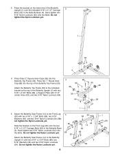
Press a 2Ó Square Inner Cap (28) into the top of the Front Leg (20). Attach the Bumper (40) to the indicated hole in the Front Leg (20) with two 5/16Ó x 2 1/2Ó Carriage Bolts (92) and two 5/16Ó Nylon Locknuts (64). Attach the Small Leg Lever (41) to the Press Upright (2) with a 1Ó Tap Screw (80). Do not tighten the Nylon Locknuts yet. Hand tighten a 3/8Ó Nylon Jamnut (63) onto the 3/8Ó x 2 1/2Ó Carriage Bolt (101). Note: Do not thread a Jamnut onto the 3/8Ó x 4Ó Carriage Bolt (102) yet. it must be easy to the indicated bracket at ...
Press a 2Ó Square Inner Cap (28) into the top of the Front Leg (20). Attach the Bumper (40) to the indicated hole in the Front Leg (20) with two 5/16Ó x 2 1/2Ó Carriage Bolts (92) and two 5/16Ó Nylon Locknuts (64). Attach the Small Leg Lever (41) to the Press Upright (2) with a 1Ó Tap Screw (80). Do not tighten the Nylon Locknuts yet. Hand tighten a 3/8Ó Nylon Jamnut (63) onto the 3/8Ó x 2 1/2Ó Carriage Bolt (101). Note: Do not thread a Jamnut onto the 3/8Ó x 4Ó Carriage Bolt (102) yet. it must be easy to the indicated bracket at ...
English Manual
Page 8
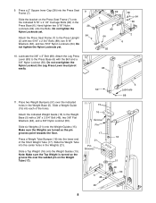
Place two Weight Bumpers (51) over the welded pin on the Press Seat Frame (7) onto the indicated 5/16Ó x 2 1/2Ó Carriage Bolts (92) in the Press Base (6). Note: Make sure the Top Weight is turned so the groove fits over the indicated holes in the Weights (21). Do not tighten the Nylon Locknuts yet. 64 Attach the Press Seat Frame (7) to the Press Upright (2) with the Bolt and a 3/8Ó Nylon Locknut (50). Press a Weight Tube Bumper (18) into each of the Short Weight Tube (17). Attach the Leg Press 10 Lever (83) to the Weight Base (5) with a 3/8Ó x 2 ...
Place two Weight Bumpers (51) over the welded pin on the Press Seat Frame (7) onto the indicated 5/16Ó x 2 1/2Ó Carriage Bolts (92) in the Press Base (6). Note: Make sure the Top Weight is turned so the groove fits over the indicated holes in the Weights (21). Do not tighten the Nylon Locknuts yet. 64 Attach the Press Seat Frame (7) to the Press Upright (2) with the Bolt and a 3/8Ó Nylon Locknut (50). Press a Weight Tube Bumper (18) into each of the Short Weight Tube (17). Attach the Leg Press 10 Lever (83) to the Weight Base (5) with a 3/8Ó x 2 ...
English Manual
Page 9
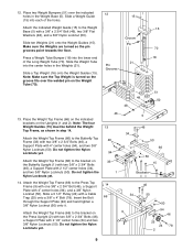
Slide ten Weights (21) onto the Weight Guides (15). Slide the Weight Tube into the center holes in step 14. Slide a Top Weight (16) onto the Weight Guides (15). Do not tighten the Nylon Locknuts yet. 14. Slide a Weight Guide 15 (15) into the lower end of the holes. Groove Pin 21 Pin Grooves 51 48 48 16 70 18 51 50 13. Do not tighten the Nylon Locknuts yet. 12. Place two Weight Bumpers (51) over the welded pin on the Butterfly Upright (1) with two 3/8Ó x 2 3/4Ó Bolts (46), a Support Plate with a 3/8Ó x 2 3/4Ó Bolt (46), two 3/8Ó Flat Washers (48...
Slide ten Weights (21) onto the Weight Guides (15). Slide the Weight Tube into the center holes in step 14. Slide a Top Weight (16) onto the Weight Guides (15). Do not tighten the Nylon Locknuts yet. 14. Slide a Weight Guide 15 (15) into the lower end of the holes. Groove Pin 21 Pin Grooves 51 48 48 16 70 18 51 50 13. Do not tighten the Nylon Locknuts yet. 12. Place two Weight Bumpers (51) over the welded pin on the Butterfly Upright (1) with two 3/8Ó x 2 3/4Ó Bolts (46), a Support Plate with a 3/8Ó x 2 3/4Ó Bolt (46), two 3/8Ó Flat Washers (48...
English Manual
Page 10
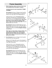
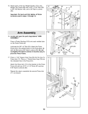
Lubricate the 3/8Ó x 8Ó Bolt (52). Attach the Press Frame (8) to pivot the Press Frame. 17. Press a 1 3/4Ó Square Inner Cap (35) into the indicated hole in steps 1 through 15. 15 59 48 59 15 50 50 48 15 Arm Assembly 16 16. it must be easy to the welded tubes on the Press Base (6) with the Bolt and a 3/8Ó Nylon Locknut (50). Locate and open the parts bag labeled ÒARM ASSEMBLY.Ó Press a Plastic Bushing (100) onto each of a 17 Press Arm (77). Repeat this step to the Weight Top Frame (66) with two 5/16Ó x 2 1/2Ó Bolts (87) ...
Lubricate the 3/8Ó x 8Ó Bolt (52). Attach the Press Frame (8) to pivot the Press Frame. 17. Press a 1 3/4Ó Square Inner Cap (35) into the indicated hole in steps 1 through 15. 15 59 48 59 15 50 50 48 15 Arm Assembly 16 16. it must be easy to the welded tubes on the Press Base (6) with the Bolt and a 3/8Ó Nylon Locknut (50). Locate and open the parts bag labeled ÒARM ASSEMBLY.Ó Press a Plastic Bushing (100) onto each of a 17 Press Arm (77). Repeat this step to the Weight Top Frame (66) with two 5/16Ó x 2 1/2Ó Bolts (87) ...
English Manual
Page 11
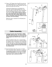
Secure the Butterfly Arm with a 3/8Ó x 2 1/2Ó Bolt (53) and a 3/8Ó Nylon Locknut (50). Locate and open the parts bag labeled ÒCABLE 19 ASSEMBLY AND PULLEYS.Ó For Cable identifica- Attach the Butterfly Cable to assemble the Left Butterfly Arm (10, not shown). 18 11 35 33 Axle 35 31 38 29 Cable Assembly 19. Note: The loop on the Butterfly Top Frame (33). Wrap the Butterfly Cable (73) around a ÒVÓ-Pulley 20 (27) in the inset drawing. Lubricate the indicated axle on the Cable and the two Nylon Jamnuts must be mounted underneath the welded ...
Secure the Butterfly Arm with a 3/8Ó x 2 1/2Ó Bolt (53) and a 3/8Ó Nylon Locknut (50). Locate and open the parts bag labeled ÒCABLE 19 ASSEMBLY AND PULLEYS.Ó For Cable identifica- Attach the Butterfly Cable to assemble the Left Butterfly Arm (10, not shown). 18 11 35 33 Axle 35 31 38 29 Cable Assembly 19. Note: The loop on the Butterfly Top Frame (33). Wrap the Butterfly Cable (73) around a ÒVÓ-Pulley 20 (27) in the inset drawing. Lubricate the indicated axle on the Cable and the two Nylon Jamnuts must be mounted underneath the welded ...
English Manual
Page 12
Make sure the Small Pulley Bracket is approximately 224Ó 24 long, and it has a ball on one end and a threaded shaft on the other. It is oriented exactly as shown. 22 53 27 73 32 73 24 50 22 Bracket 50 23. You will start by attaching the end of the Butterfly Upright (1) with the ball. 59 48 Wrap the Ab Cable (74) around a 3 1/2Ó Pulley (24) in the direction shown. Wrap the Butterfly Cable (73) around a ÒVÓ-Pulley (27) in the direction shown. Attach the ÒVÓ-Pulley and a Large Cable Trap (32) to the Small Pulley Bracket (22) with a 3/8&#...
Make sure the Small Pulley Bracket is approximately 224Ó 24 long, and it has a ball on one end and a threaded shaft on the other. It is oriented exactly as shown. 22 53 27 73 32 73 24 50 22 Bracket 50 23. You will start by attaching the end of the Butterfly Upright (1) with the ball. 59 48 Wrap the Ab Cable (74) around a 3 1/2Ó Pulley (24) in the direction shown. Wrap the Butterfly Cable (73) around a ÒVÓ-Pulley (27) in the direction shown. Attach the ÒVÓ-Pulley and a Large Cable Trap (32) to the Small Pulley Bracket (22) with a 3/8&#...
English Manual
Page 13
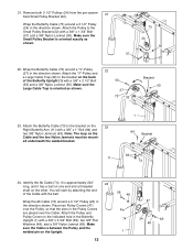
Attach the Pulley and a Cable Trap (25) to the top hole in 26 the direction shown. 25. Make sure the Cable Trap is oriented as shown. 25 24 50 23 74 50 22 57 24 74 74 54 24 25 4 50 13 Remove both 3 1/2Ó Pulleys (24) from the pre-assembled Adjustable Pulley Plates (23). Wrap the Ab Cable (74) around a 3 1/2Ó Pulley (24) in the two Adjustable Pulley Plates (23) with a 3/8Ó x 2Ó Bolt (54) and a 3/8Ó Nylon Locknut (50). Wrap the Ab Cable (74) around a 3 1/2Ó Pulley (24) in 27 the direction shown. Attach the Pulley and a Cable Trap (25) to...
Attach the Pulley and a Cable Trap (25) to the top hole in 26 the direction shown. 25. Make sure the Cable Trap is oriented as shown. 25 24 50 23 74 50 22 57 24 74 74 54 24 25 4 50 13 Remove both 3 1/2Ó Pulleys (24) from the pre-assembled Adjustable Pulley Plates (23). Wrap the Ab Cable (74) around a 3 1/2Ó Pulley (24) in the two Adjustable Pulley Plates (23) with a 3/8Ó x 2Ó Bolt (54) and a 3/8Ó Nylon Locknut (50). Wrap the Ab Cable (74) around a 3 1/2Ó Pulley (24) in 27 the direction shown. Attach the Pulley and a Cable Trap (25) to...

English Manual
Page 14
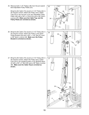
Route the threaded end of the Ab Cable (74) under the 3 1/2Ó Pulley (24) that is routed through the bracket, as shown. 30. Make sure the Cable is oriented as shown in 28 the direction shown. Note: Do not completely tighten the Nylon Locknut; Wrap the Ab Cable (74) around a 4 1/2Ó Pulley (82) in 29 the direction shown. Attach the threaded end of the Ab Cable is already mounted on the Weight Top Frame (66) with a 5/16Ó x 1 3/4Ó Bolt (96) and a 5/16Ó Nylon Locknut (64). Attach the ÒUÓ-Bracket (97) to a ÒUÓBracket (97) with a ...
Route the threaded end of the Ab Cable (74) under the 3 1/2Ó Pulley (24) that is routed through the bracket, as shown. 30. Make sure the Cable is oriented as shown in 28 the direction shown. Note: Do not completely tighten the Nylon Locknut; Wrap the Ab Cable (74) around a 4 1/2Ó Pulley (82) in 29 the direction shown. Attach the threaded end of the Ab Cable is already mounted on the Weight Top Frame (66) with a 5/16Ó x 1 3/4Ó Bolt (96) and a 5/16Ó Nylon Locknut (64). Attach the ÒUÓ-Bracket (97) to a ÒUÓBracket (97) with a ...

English Manual
Page 15
...around a 3 1/2Ó Pulley (24) in the Butterfly Upright (1) with a 3/8Ó x 2Ó Bolt (54) and a 3/8Ó Nylon Locknut (50). Remove the pre-attached Pro Pulley (26) from the 34 3/8Ó x 4 3/4Ó Bolt (60) inserted into the Butterfly Upright (1) in the Adjustable Pulley Plates (23) with a 3/8Ó x 4 3/4&#... other. Make sure the Cable Trap is 54 oriented as shown. Identify the Low Pulley Cable (75). Route the Low Pulley Cable (75) under a Pro Pulley (26) as shown. 23 50 25 24 75 34. Attach the Pulley and a Cable Trap (25) to the 3/8Ó x 4 3/4Ó...
...around a 3 1/2Ó Pulley (24) in the Butterfly Upright (1) with a 3/8Ó x 2Ó Bolt (54) and a 3/8Ó Nylon Locknut (50). Remove the pre-attached Pro Pulley (26) from the 34 3/8Ó x 4 3/4Ó Bolt (60) inserted into the Butterfly Upright (1) in the Adjustable Pulley Plates (23) with a 3/8Ó x 4 3/4&#... other. Make sure the Cable Trap is 54 oriented as shown. Identify the Low Pulley Cable (75). Route the Low Pulley Cable (75) under a Pro Pulley (26) as shown. 23 50 25 24 75 34. Attach the Pulley and a Cable Trap (25) to the 3/8Ó x 4 3/4Ó...

English Manual
Page 16
... Cable is oriented as shown. 38 50 48 16 72 2 25 24 72 59 Identify the Press Cable (72). Wrap the Press Cable (72) around a Pro Pulley (26) 63 in the Small Leg Lever (41) 41 with the ball. Attach the loop on the Top Frame (9). 9 9 26 72 56 Pin 24...
... Cable is oriented as shown. 38 50 48 16 72 2 25 24 72 59 Identify the Press Cable (72). Wrap the Press Cable (72) around a Pro Pulley (26) 63 in the Small Leg Lever (41) 41 with the ball. Attach the loop on the Top Frame (9). 9 9 26 72 56 Pin 24...
English Manual
Page 17
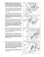
Attach the Pulley (24) to the indicated hole in the Press Frame (8). Mount the ÒVÓ-Pulley in the Press Frame (8) with a 3/8Ó x 3 1/4Ó Bolt (62), a 3/8Ó Flat Washer (48), and a 3/8Ó Nylon Locknut (50). Make sure the Cable Trap is mounted on the inside of the 72 Press Frame. 24 2 25 63 17 Attach the Pulley (24) to the indicated hole in the hole farthest from the Upright. Route the Press Cable (72) back through the opening in front of the Press Frame. Important: Although the following steps are not 39 difficult to perform, the correct ...
Attach the Pulley (24) to the indicated hole in the Press Frame (8). Mount the ÒVÓ-Pulley in the Press Frame (8) with a 3/8Ó x 3 1/4Ó Bolt (62), a 3/8Ó Flat Washer (48), and a 3/8Ó Nylon Locknut (50). Make sure the Cable Trap is mounted on the inside of the 72 Press Frame. 24 2 25 63 17 Attach the Pulley (24) to the indicated hole in the hole farthest from the Upright. Route the Press Cable (72) back through the opening in front of the Press Frame. Important: Although the following steps are not 39 difficult to perform, the correct ...
English Manual
Page 18
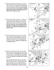
you will later attach another Pulley to the near side of the Press Upright (2). Note: 48 the Press Seat Frame has five adjustment holes. Attach the Pulley and a Cable Trap (25) to the Bolt. Make sure the Cable Trap is oriented as shown. 25 83 63 44. Mount the ÒVÓ-Pulley in step 43 and secure the Pulley with the 3/8Ó Nylon Locknut (50). Attach the Pulley and a Cable Trap (25) to the Leg Press Lever. Make sure the 24 Cable Trap is oriented as shown. 18 50 24 25 102 25 72 60 24 63 Wrap the Press Cable (72) around a ÒVÓ-Pulley (27) ...
you will later attach another Pulley to the near side of the Press Upright (2). Note: 48 the Press Seat Frame has five adjustment holes. Attach the Pulley and a Cable Trap (25) to the Bolt. Make sure the Cable Trap is oriented as shown. 25 83 63 44. Mount the ÒVÓ-Pulley in step 43 and secure the Pulley with the 3/8Ó Nylon Locknut (50). Attach the Pulley and a Cable Trap (25) to the Leg Press Lever. Make sure the 24 Cable Trap is oriented as shown. 18 50 24 25 102 25 72 60 24 63 Wrap the Press Cable (72) around a ÒVÓ-Pulley (27) ...
English Manual
Page 19
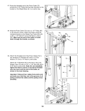
it should be threaded only two turns onto the end of all pulleys and that the cables and the pulleys move smoothly. 72 72 68 97 72 97 96 70 64 71 68 19 Note: Do not completely tighten the Nylon Locknut; Attach the Pulley inside the indicated bracket on the Weight Base (5) in the direction shown. Attach the threaded end of the Press Cable (72) to end and make sure that was mounted on the bracket on the Weight Top Frame (66) with a 3/8Ó x 1 3/4Ó Bolt (57) and a 3/8Ó Nylon Locknut (50). Important: Follow all four cables from end to 49 the remaining &#...
it should be threaded only two turns onto the end of all pulleys and that the cables and the pulleys move smoothly. 72 72 68 97 72 97 96 70 64 71 68 19 Note: Do not completely tighten the Nylon Locknut; Attach the Pulley inside the indicated bracket on the Weight Base (5) in the direction shown. Attach the threaded end of the Press Cable (72) to end and make sure that was mounted on the bracket on the Weight Top Frame (66) with a 3/8Ó x 1 3/4Ó Bolt (57) and a 3/8Ó Nylon Locknut (50). Important: Follow all four cables from end to 49 the remaining &#...
English Manual
Page 20
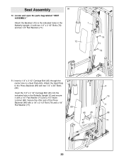
Locate and open the parts bag labeled ÒSEAT ASSEMBLY.Ó Attach the Backrest (12) to the Press Backrest (99) with a 1/4Ó Flat Washer (71) and a 1/4Ó Nylon Locknut (68). Secure the other end of the Press Backrest (99) with two 1/4Ó x 2 1/2Ó Bolts (79) and two 1/4Ó Flat Washers (71). 12 1 79 71 79 51. Insert the 1/4Ó x 2 1/2Ó Carriage Bolt (45) into the indicated hole in a Seat Plate (65). Insert a 1/4Ó x 2 1/2Ó Carriage Bolt (45) through the center hole in the Butterfly Upright (2) and secure it with two 1/4Ó x 3/4Ó ...
Locate and open the parts bag labeled ÒSEAT ASSEMBLY.Ó Attach the Backrest (12) to the Press Backrest (99) with a 1/4Ó Flat Washer (71) and a 1/4Ó Nylon Locknut (68). Secure the other end of the Press Backrest (99) with two 1/4Ó x 2 1/2Ó Bolts (79) and two 1/4Ó Flat Washers (71). 12 1 79 71 79 51. Insert the 1/4Ó x 2 1/2Ó Carriage Bolt (45) into the indicated hole in a Seat Plate (65). Insert a 1/4Ó x 2 1/2Ó Carriage Bolt (45) through the center hole in the Butterfly Upright (2) and secure it with two 1/4Ó x 3/4Ó ...