

Uk Manual
Page 3
... beneath it to tip. 12. The weight system is especially important for home use only. Never release the ankle strap, leg lever, squat bar, leg press, or handles while weights are on the pulleys at any other type of weight to support a maximum user weight of 135 kg (300 lbs.). 13...
... beneath it to tip. 12. The weight system is especially important for home use only. Never release the ankle strap, leg lever, squat bar, leg press, or handles while weights are on the pulleys at any other type of weight to support a maximum user weight of 135 kg (300 lbs.). 13...

Uk Manual
Page 5
... the weight system, make sure you assemble it will go smoothly. Do not dispose of its weight and size, the weight system should be used. Press the two Base Caps 74 (38) onto the Base (1). 38 1 38 5 Before beginning assembly, carefully read the following tools (not included): • Two adjustable spanners...
... the weight system, make sure you assemble it will go smoothly. Do not dispose of its weight and size, the weight system should be used. Press the two Base Caps 74 (38) onto the Base (1). 38 1 38 5 Before beginning assembly, carefully read the following tools (not included): • Two adjustable spanners...

Uk Manual
Page 6
Press the 110mm Round Inner Cap (42) into the Upright (3). 2 42 Set the Upright (3) onto the Base (1). Attach the Base Plate (2) to the Base (1) with the 3 four M4 x 40mm Screws (46), and two M4 x 64mm Screws (81). 2 46 6 1 46 81 81 46 Have a second person hold the Upright until this step is completed. Attach the Upright (3) to the Base (1) with the three M8 x 45mm Bolts (57), three M8 Nylon Locknuts (74), and four M10 x 25mm Screws (58). 3 58 58 74 57 74 1 57 3. 2.
Press the 110mm Round Inner Cap (42) into the Upright (3). 2 42 Set the Upright (3) onto the Base (1). Attach the Base Plate (2) to the Base (1) with the 3 four M4 x 40mm Screws (46), and two M4 x 64mm Screws (81). 2 46 6 1 46 81 81 46 Have a second person hold the Upright until this step is completed. Attach the Upright (3) to the Base (1) with the three M8 x 45mm Bolts (57), three M8 Nylon Locknuts (74), and four M10 x 25mm Screws (58). 3 58 58 74 57 74 1 57 3. 2.

Uk Manual
Page 9
... Swivel Arm (16). Reattach the Swivel Arm (16) to the Upright (3) with the M4 x 5mm Screw (69). 8 3 8 58 16 30 69 58 9. Make sure the Press Arm Cable (30) is routed under the indicated welded rods. Welded 16 Rod 71 73 30 75 71 25 25 Welded Rod 22 10. 8. Attach... (61), two M10 Washers (71), two 5mm Spacers (25), two Finger Guards (27), and an M10 Nylon Locknut (73). Attach a "V"-pulley (22) to the left Press Arm (8) with an M10 x 64mm Button Bolt (75), two M10 9 Washers (71), two 5mm Spacers (25), and an M10 Nylon Locknut (73). Orient the finger...
... Swivel Arm (16). Reattach the Swivel Arm (16) to the Upright (3) with the M4 x 5mm Screw (69). 8 3 8 58 16 30 69 58 9. Make sure the Press Arm Cable (30) is routed under the indicated welded rods. Welded 16 Rod 71 73 30 75 71 25 25 Welded Rod 22 10. 8. Attach... (61), two M10 Washers (71), two 5mm Spacers (25), two Finger Guards (27), and an M10 Nylon Locknut (73). Attach a "V"-pulley (22) to the left Press Arm (8) with an M10 x 64mm Button Bolt (75), two M10 9 Washers (71), two 5mm Spacers (25), and an M10 Nylon Locknut (73). Orient the finger...

Uk Manual
Page 10
Wrap the Press Arm Cable (30) over a 3 1/2" Pulley (24). Make sure the Finger Guards are oriented as shown. Attach ...62) and an M10 Nylon Locknut (73) at the indicated hole. Wrap the Press Arm Cable (30) under a 3 1/2" Pulley (24). Make sure the Cable Trap is oriented to hold the Press Arm Cable (30) in the groove of the Pulley. 4 24 28 65... 73 30 13. Wrap the Press Arm Cable (30) around a 3 1/2" Pulley (24) and route the Cable through ...
Wrap the Press Arm Cable (30) over a 3 1/2" Pulley (24). Make sure the Finger Guards are oriented as shown. Attach ...62) and an M10 Nylon Locknut (73) at the indicated hole. Wrap the Press Arm Cable (30) under a 3 1/2" Pulley (24). Make sure the Cable Trap is oriented to hold the Press Arm Cable (30) in the groove of the Pulley. 4 24 28 65... 73 30 13. Wrap the Press Arm Cable (30) around a 3 1/2" Pulley (24) and route the Cable through ...

Uk Manual
Page 11
... Trap 14 (28) to hold the Cable in the groove of the Pulley. 28 65 24 30 73 4 15. 14. Route the Press Arm Cable (30) through the Press Arm as shown. Make sure the Cable Trap is oriented to the Top Frame (4) with four M10 x 25mm Screws (58). 16 Remove the... Arm (16). Using the wire that is oriented to the Upright (3) with an M10 x 45mm Bolt (65) and an M10 Nylon Locknut (73). Attach the Press Arm (8) with the wire to hold the Cable in the groove of the Pulley. 65 28 24 15 30 4 73 16. Make sure the Cable...
... Trap 14 (28) to hold the Cable in the groove of the Pulley. 28 65 24 30 73 4 15. 14. Route the Press Arm Cable (30) through the Press Arm as shown. Make sure the Cable Trap is oriented to the Top Frame (4) with four M10 x 25mm Screws (58). 16 Remove the... Arm (16). Using the wire that is oriented to the Upright (3) with an M10 x 45mm Bolt (65) and an M10 Nylon Locknut (73). Attach the Press Arm (8) with the wire to hold the Cable in the groove of the Pulley. 65 28 24 15 30 4 73 16. Make sure the Cable...

Uk Manual
Page 12
...) is in the groove of the Pulley. 17 73 25 71 30 27 8 23 27 61 71 25 18. Attach a "V"-pulley (22) to the right Press Arm (8) with an M10 x 53mm Button Bolt (61), two M10 Washers (71), two 5mm Spacers (25), two Finger Guards (27), and an M10 Nylon Locknut... Swivel Arm (16) with the two M6 x 16mm Screws (60) and the M6 x 19 127mm Screw (79). 18 79 60 60 3 12 Make sure the Press Arm Cable (30) is routed under the indicated welded rods. Attach the Backrest (18) to the Upright (3) with an M10 x 64mm Button Bolt (75), two...
...) is in the groove of the Pulley. 17 73 25 71 30 27 8 23 27 61 71 25 18. Attach a "V"-pulley (22) to the right Press Arm (8) with an M10 x 53mm Button Bolt (61), two M10 Washers (71), two 5mm Spacers (25), two Finger Guards (27), and an M10 Nylon Locknut... Swivel Arm (16) with the two M6 x 16mm Screws (60) and the M6 x 19 127mm Screw (79). 18 79 60 60 3 12 Make sure the Press Arm Cable (30) is routed under the indicated welded rods. Attach the Backrest (18) to the Upright (3) with an M10 x 64mm Button Bolt (75), two...

Uk Manual
Page 14
... worn parts immediately. To use . 37 30 32 B 1 32 To attach a Handle (33), first attach the pulley housings to an Extension Cable (31) or the Press Arm Cable (30) with 37 a Cable Clip (37). 33 37 30 14 Then, attach the Handle to an Extension Cable (31) with a Cable Clip (37... shown) can be attached to the weight system (see the correct form for important information about how to the hooks on the sides of the Press Arm Cable (30) with a damp cloth and a mild, non-abrasive detergent. Do not use a high pulley, slide the hook on the Pulley Housing (32) onto...
... worn parts immediately. To use . 37 30 32 B 1 32 To attach a Handle (33), first attach the pulley housings to an Extension Cable (31) or the Press Arm Cable (30) with 37 a Cable Clip (37). 33 37 30 14 Then, attach the Handle to an Extension Cable (31) with a Cable Clip (37... shown) can be attached to the weight system (see the correct form for important information about how to the hooks on the sides of the Press Arm Cable (30) with a damp cloth and a mild, non-abrasive detergent. Do not use a high pulley, slide the hook on the Pulley Housing (32) onto...

Uk Manual
Page 16
... with only one Extension Cable attached to it. 7 31 37 37 34 37 31 CABLE DIAGRAM The cable diagram shows the proper routing of the Press Arm Cable (30). The numbers show the correct route for the Cable. Note: For less resistance, the Leg Lever can be used with another ...Cable Clip. If the Cable has not been correctly routed, the weight system will not function properly and damage may occur. Press Arm Cable (30) 7 6 4 3 9 8 5 2 1 16 Adjust the Extension Strap to make sure that the Cable has been assembled correctly. ATTACHING THE LEG LEVER To use the...
... with only one Extension Cable attached to it. 7 31 37 37 34 37 31 CABLE DIAGRAM The cable diagram shows the proper routing of the Press Arm Cable (30). The numbers show the correct route for the Cable. Note: For less resistance, the Leg Lever can be used with another ...Cable Clip. If the Cable has not been correctly routed, the weight system will not function properly and damage may occur. Press Arm Cable (30) 7 6 4 3 9 8 5 2 1 16 Adjust the Extension Strap to make sure that the Cable has been assembled correctly. ATTACHING THE LEG LEVER To use the...
Uk Manual
Page 21
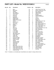
...23 4 2 3/4" Pulley 24 5 3 1/2" Pulley 25 8 5mm Spacer 26 2 Half Finger Guard 27 4 Finger Guard 28 5 Cable Trap 29 4 Pulley Cover 30 1 Press Arm Cable 31 2 Extension Cable 32 2 Pulley Housing 33 2 Handle 34 2 Extension Strap 35 1 Squat Bar Pad 36 1 Ankle Strap 37 6 Cable Clip 38 2 Base... Cap 39 4 64mm Round Outer Cap 40 4 19mm Round Inner Cap 41 2 51mm Round Inner Cap 42 1 110mm Round Inner Cap 43 2 Press Arm Cap 44 2 32mm Round Inner Cap 45 1 51mm x 76mm Inner Cap 46 4 M4 x 40mm Screw 47 2 25mm Spacer 48 2 38mm ...
...23 4 2 3/4" Pulley 24 5 3 1/2" Pulley 25 8 5mm Spacer 26 2 Half Finger Guard 27 4 Finger Guard 28 5 Cable Trap 29 4 Pulley Cover 30 1 Press Arm Cable 31 2 Extension Cable 32 2 Pulley Housing 33 2 Handle 34 2 Extension Strap 35 1 Squat Bar Pad 36 1 Ankle Strap 37 6 Cable Clip 38 2 Base... Cap 39 4 64mm Round Outer Cap 40 4 19mm Round Inner Cap 41 2 51mm Round Inner Cap 42 1 110mm Round Inner Cap 43 2 Press Arm Cap 44 2 32mm Round Inner Cap 45 1 51mm x 76mm Inner Cap 46 4 M4 x 40mm Screw 47 2 25mm Spacer 48 2 38mm ...


