
English Manual
Page 2
WEIDER is a registered trademark of this manual. Remove the PART IDENTIFICATION CHART and the PART LIST/EXPLODED DRAWING before beginning assembly. TABLE OF CONTENTS IMPORTANT PRECAUTIONS 3 BEFORE YOU BEGIN 4 ASSEMBLY 5 ADJUSTMENTS 20 WEIGHT RESISTANCE CHART 23 CABLE DIAGRAM 24 EXERCISE GUIDELINES 26 ORDERING REPLACEMENT PARTS Back Cover FULL 90 DAY WARRANTY Back Cover Note: A PART IDENTIFICATION CHART and a PART LIST/EXPLODED DRAWING are attached in the center of ICON Health & Fitness, Inc. 2
WEIDER is a registered trademark of this manual. Remove the PART IDENTIFICATION CHART and the PART LIST/EXPLODED DRAWING before beginning assembly. TABLE OF CONTENTS IMPORTANT PRECAUTIONS 3 BEFORE YOU BEGIN 4 ASSEMBLY 5 ADJUSTMENTS 20 WEIGHT RESISTANCE CHART 23 CABLE DIAGRAM 24 EXERCISE GUIDELINES 26 ORDERING REPLACEMENT PARTS Back Cover FULL 90 DAY WARRANTY Back Cover Note: A PART IDENTIFICATION CHART and a PART LIST/EXPLODED DRAWING are attached in the center of ICON Health & Fitness, Inc. 2

English Manual
Page 3
... fingers clear of 300 pounds. 10. WARNING: Before beginning this or any worn parts immediately. 6. This is designed to support a maximum user weight of this product. 3 If the cables bind while you feel pain or dizziness while exercising, stop immediately and make sure that the cables are ... that does not use of all instructions in the accompanying literature before using . Always disconnect the lat bar from moving parts. 8. Use the weight system only as described in this manual and in this manual. 11. Mountain Time, to protect the floor. 5. Keep hands and feet away...
... fingers clear of 300 pounds. 10. WARNING: Before beginning this or any worn parts immediately. 6. This is designed to support a maximum user weight of this product. 3 If the cables bind while you feel pain or dizziness while exercising, stop immediately and make sure that the cables are ... that does not use of all instructions in the accompanying literature before using . Always disconnect the lat bar from moving parts. 8. Use the weight system only as described in this manual and in this manual. 11. Mountain Time, to protect the floor. 5. Keep hands and feet away...

English Manual
Page 4
... attached to achieve the results you , please note the product model number and serial number before using the weight system. until 6 p.m. If you for selecting the versatile WEIDER® PRO 3200 weight system. To help you to the weight system (see the front cover of the body. they do not correspond to develop every major muscle...
... attached to achieve the results you , please note the product model number and serial number before using the weight system. until 6 p.m. If you for selecting the versatile WEIDER® PRO 3200 weight system. To help you to the weight system (see the front cover of the body. they do not correspond to develop every major muscle...
English Manual
Page 5
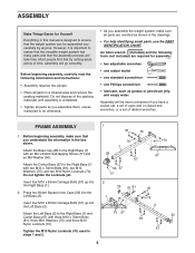
... of the packing materials until assembly is completed. • Tighten all parts as you assemble them, unless instructed to ensure that the weight system can be assembled successfully by setting aside plenty of ratchet wrenches. Before beginning assembly, make sure all parts in a cleared area and...(57) up into the Left Base (2). Most people find that by anyone. Attach the Base Cap (28) to realize that the versatile weight system has many parts and that the assembly process will take time. Before beginning assembly, carefully read the following tools (not included) are oriented...
... of the packing materials until assembly is completed. • Tighten all parts as you assemble them, unless instructed to ensure that the weight system can be assembled successfully by setting aside plenty of ratchet wrenches. Before beginning assembly, make sure all parts in a cleared area and...(57) up into the Left Base (2). Most people find that by anyone. Attach the Base Cap (28) to realize that the versatile weight system has many parts and that the assembly process will take time. Before beginning assembly, carefully read the following tools (not included) are oriented...

English Manual
Page 7
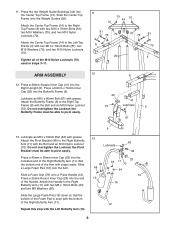
... M10 Nylon Locknuts (70) yet. 5 Short 60 Side 60 5 75 6 73 70 75 75 70 75 6. Set two Weight Bumpers (83) over the indicated holes in the Center Base (67). 5. Attach the Weight Guides to the Right Upright (6) with the short side of the Left Seat Frame (29). Attach the Right Seat... (70). Orient the Right Seat Frame (5) with two M10 x 85mm Bolts (60), two M10 Washers (75), and two M10 Nylon Locknuts (70). Insert the two Weight Guides (20) into the end of the adjustment tube on top.
... M10 Nylon Locknuts (70) yet. 5 Short 60 Side 60 5 75 6 73 70 75 75 70 75 6. Set two Weight Bumpers (83) over the indicated holes in the Center Base (67). 5. Attach the Weight Guides to the Right Upright (6) with the short side of the Left Seat Frame (29). Attach the Right Seat... (70). Orient the Right Seat Frame (5) with two M10 x 85mm Bolts (60), two M10 Washers (75), and two M10 Nylon Locknuts (70). Insert the two Weight Guides (20) into the end of the adjustment tube on top.

English Manual
Page 8
...75 81 8 Press two 50mm x 70mm Inner Caps (22) into the end of the Left Top Frame (3). Insert the Weight Tube into the bottom of Weights (72). Slide the Top Weight onto the Weight Guides (20), with the pin grooves on the bottom. 20 74 Pin Groove Lubricate Holes 82 32 72 9. Attach the...x 70mm Bolts (81), two M10 Washers (75), and two M10 Nylon Locknuts (70). Press the Weight Tube Bumper (32) into the center hole in the Top Weight (74). Slide the eight Weights (72) onto the Weight 8 Guides (20) with the pin groove on the side shown. Lubricate the indicated holes in the stack...
...75 81 8 Press two 50mm x 70mm Inner Caps (22) into the end of the Left Top Frame (3). Insert the Weight Tube into the bottom of Weights (72). Slide the Top Weight onto the Weight Guides (20), with the pin grooves on the bottom. 20 74 Pin Groove Lubricate Holes 82 32 72 9. Attach the...x 70mm Bolts (81), two M10 Washers (75), and two M10 Nylon Locknuts (70). Press the Weight Tube Bumper (32) into the center hole in the Top Weight (74). Slide the eight Weights (72) onto the Weight 8 Guides (20) with the pin groove on the side shown. Lubricate the indicated holes in the stack...
English Manual
Page 9
Slide the Center Top Frame onto the Weight Guides (20). Press a 50mm x 70mm Inner Cap (22) into the Right Upright (6). Attach the Butterfly Frame (9) to the Right Top Frame (8) with grease. Lubricate an ... Right Top Frame (8) with the bottom of the Arm with grease. Do not overtighten the Locknut; Do not overtighten the Locknut; 11. Press the two Weight Guide Bushings (44) into the end of the Right Butterfly Arm (11). Attach the Center Top Frame (14) to the Right Butterfly Arm (11) with...
Slide the Center Top Frame onto the Weight Guides (20). Press a 50mm x 70mm Inner Cap (22) into the Right Upright (6). Attach the Butterfly Frame (9) to the Right Top Frame (8) with grease. Lubricate an ... Right Top Frame (8) with the bottom of the Arm with grease. Do not overtighten the Locknut; Do not overtighten the Locknut; 11. Press the two Weight Guide Bushings (44) into the end of the Right Butterfly Arm (11). Attach the Center Top Frame (14) to the Right Butterfly Arm (11) with...

English Manual
Page 11
...). Route the High Cable (45) around a 90mm Pulley (38). Note: To complete this step is turned to hold the Cable in the groove of the weight system, with an M10 x 70mm Bolt (81), two M10 Washers (75), two 13mm Spacers (34), and an M10 Nylon Locknut (70). Note: The following drawings...
...). Route the High Cable (45) around a 90mm Pulley (38). Note: To complete this step is turned to hold the Cable in the groove of the weight system, with an M10 x 70mm Bolt (81), two M10 Washers (75), two 13mm Spacers (34), and an M10 Nylon Locknut (70). Note: The following drawings...

English Manual
Page 12
21. Attach the Small "U"-Bracket (79) to the Weight Tube (82) with an M10 x 70mm Bolt (81), two M10 Washers (75), two 13mm Spacers (34), and an M10 Nylon Locknut (70). 23 81 80 ...75 70 80 95 75 36 24 34 75 81 38 75 70 34 95 30 12 the Weight Tube should be able to the Small "U"-Bracket (79) with aM10 x 70mm Bolt (81), two M10 Washers (75), two Long Spacers (80), and an M10...
21. Attach the Small "U"-Bracket (79) to the Weight Tube (82) with an M10 x 70mm Bolt (81), two M10 Washers (75), two 13mm Spacers (34), and an M10 Nylon Locknut (70). 23 81 80 ...75 70 80 95 75 36 24 34 75 81 38 75 70 34 95 30 12 the Weight Tube should be able to the Small "U"-Bracket (79) with aM10 x 70mm Bolt (81), two M10 Washers (75), two Long Spacers (80), and an M10...
English Manual
Page 20
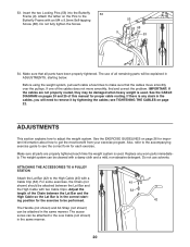
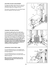
...the High Cable so the Lat Bar is used . Do not fully tighten the Screw. 53 68 9 53 54. Before using the weight system, pull each time the weight system is in ADJUSTMENTS, starting position for each exercise. If there is used . Replace any slack in the cables, you will be ... of all parts have been properly tightened. See the EXERCISE GUIDELINES on the Pins to the Low Cable (not shown) in the same manner. The weight system can be attached to the Butterfly Frame with a Cable Clip (52). ATTACHING THE ACCESSORIES TO A PULLEY STATION Attach the Lat Bar (42) to ...
...the High Cable so the Lat Bar is used . Do not fully tighten the Screw. 53 68 9 53 54. Before using the weight system, pull each time the weight system is in ADJUSTMENTS, starting position for each exercise. If there is used . Replace any slack in the cables, you will be ... of all parts have been properly tightened. See the EXERCISE GUIDELINES on the Pins to the Low Cable (not shown) in the same manner. The weight system can be attached to the Butterfly Frame with a Cable Clip (52). ATTACHING THE ACCESSORIES TO A PULLEY STATION Attach the Lat Bar (42) to ...
English Manual
Page 21
...53) into the press holes in increments of 12.5 pounds. Raise or lower the Seat to find the actual amount of resistance at each weight station. Note: Due to the cables and pulleys, the actual amount of resistance at each exercise station may vary from 6 pounds to insert the.... 21 72 86 Butterfly Holes 53 9 6 11 Press Holes 10 ADJUSTING THE SEAT AND BACKREST To change the weight setting of the weight stack, insert the Weight Pin (86) under the desired Weight (72). Make sure that the Locking Pins (53) are fully inserted into the butterfly holes in the same manner...
...53) into the press holes in increments of 12.5 pounds. Raise or lower the Seat to find the actual amount of resistance at each weight station. Note: Due to the cables and pulleys, the actual amount of resistance at each exercise station may vary from 6 pounds to insert the.... 21 72 86 Butterfly Holes 53 9 6 11 Press Holes 10 ADJUSTING THE SEAT AND BACKREST To change the weight setting of the weight stack, insert the Weight Pin (86) under the desired Weight (72). Make sure that the Locking Pins (53) are fully inserted into the butterfly holes in the same manner...
English Manual
Page 22
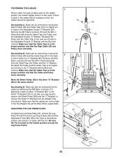
... (56). Re-attach the Pulley and the Cable Trap to the higher set of holes in the cables before resistance is first used on the weight system, can be tightened. Make sure that the Cable Trap is in a "U"-Bracket (85). See drawing B. Slack can be removed from the cables by moving... drawing A. Slack can stretch slightly when it in the same manner. Remove the M10 Nylon Locknut (70) and the M10 x 50mm Bolt (62) from the Weight Tube (not shown). See drawing B. A 70 56 91 62 45 38 B 74 70 71 38 62 79 85 87 79 31 30 22 Re-attach...
... (56). Re-attach the Pulley and the Cable Trap to the higher set of holes in the cables before resistance is first used on the weight system, can be tightened. Make sure that the Cable Trap is in a "U"-Bracket (85). See drawing B. Slack can be removed from the cables by moving... drawing A. Slack can stretch slightly when it in the same manner. Remove the M10 Nylon Locknut (70) and the M10 x 50mm Bolt (62) from the Weight Tube (not shown). See drawing B. A 70 56 91 62 45 38 B 74 70 71 38 62 79 85 87 79 31 30 22 Re-attach...
English Manual
Page 23
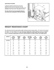
.... "Top" refers to differences in the same manner. 16 100 29 102 WEIGHT RESISTANCE CHART The chart below shows the approximate weight resistance at each station may vary due to the 6-pound top weight. Note: The actual resistance at each butterfly arm. ADJUSTING THE SEATS to the.... The other Seat (16) and the adjustable Backrest (not shown) can be adjusted in individual weight plates as well as friction between the cables, pulleys, and weight guides. Weight resistance shown for the butterfly arm station is for each exercise station. The other numbers refer to adjust the ...
.... "Top" refers to differences in the same manner. 16 100 29 102 WEIGHT RESISTANCE CHART The chart below shows the approximate weight resistance at each station may vary due to the 6-pound top weight. Note: The actual resistance at each butterfly arm. ADJUSTING THE SEATS to the.... The other Seat (16) and the adjustable Backrest (not shown) can be adjusted in individual weight plates as well as friction between the cables, pulleys, and weight guides. Weight resistance shown for the butterfly arm station is for each exercise station. The other numbers refer to adjust the ...
English Manual
Page 24
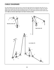
... cable diagrams below show the correct route for each cable. Make sure that the cables and the cable traps have not been correctly routed, the weight system will not function properly and damage may occur.
... cable diagrams below show the correct route for each cable. Make sure that the cables and the cable traps have not been correctly routed, the weight system will not function properly and damage may occur.
English Manual
Page 26
... exercise you feeling exhausted. On the exercise guide accompanying this manual you will continually adapt and grow as the number of weight training and aerobic exercise will leave you perform. The repetitions in any time while exercising, stop immediately and begin cooling down... for you want to session. A "set . Select exercises for every major muscle group, emphasizing areas that is : • Plan weight training workouts on Tuesday and Thursday. • Rest from session to develop most. This requires moving through the full range of motion for...
... exercise you feeling exhausted. On the exercise guide accompanying this manual you will continually adapt and grow as the number of weight training and aerobic exercise will leave you perform. The repetitions in any time while exercising, stop immediately and begin cooling down... for you want to session. A "set . Select exercises for every major muscle group, emphasizing areas that is : • Plan weight training workouts on Tuesday and Thursday. • Rest from session to develop most. This requires moving through the full range of motion for...

English Manual
Page 27
... each set . Move slowly as you stretch and do not bounce. Ease into each set for a toning work- Record your weight and key body measurements at the end of your arms and legs. MUSCLE CHART A. Sternomastoid (neck) B. Pectoralis Major (chest...) A C. Brachioradials (forearm) C F. Rectus Abdominus (stomach) G M. Plan to increase flexibility. list the date, the exercises performed, the weight used, and the numbers of thigh) E J. Sartorius (front of sets and repetitions completed. Soleus (front of calf) N O P Q R S T U V W 27...
... each set . Move slowly as you stretch and do not bounce. Ease into each set for a toning work- Record your weight and key body measurements at the end of your arms and legs. MUSCLE CHART A. Sternomastoid (neck) B. Pectoralis Major (chest...) A C. Brachioradials (forearm) C F. Rectus Abdominus (stomach) G M. Plan to increase flexibility. list the date, the exercises performed, the weight used, and the numbers of thigh) E J. Sartorius (front of sets and repetitions completed. Soleus (front of calf) N O P Q R S T U V W 27...

English Manual
Page 30
... Handle M6 x 16mm Bolt Center Top Frame Backrest Seat Long Pad Tube Foam Pad Large Foam Pad Weight Guide Support Plate 50mm x 70mm Inner Cap 40mm x 50mm Inner Cap 25mm Round Inner Cap Bumper ...M8 Washer 19mm Round Inner Cap Base Cap Left Seat Frame Leg Press Frame Leg Press Plate Weight Tube Bumper 50mm Square Inner Cap 13mm Spacer M6 Washer Left Leg Left Base Plate 90mm Pulley ..."V"-Pulley Long Cable Trap 38mm Square Inner Cap Lat Bar Handgrip Weight Guide Bushing High Cable Butterfly Cable Low Cable Pivot Bracket Chain M5 Washer Handle Cable Clip Locking ...
... Handle M6 x 16mm Bolt Center Top Frame Backrest Seat Long Pad Tube Foam Pad Large Foam Pad Weight Guide Support Plate 50mm x 70mm Inner Cap 40mm x 50mm Inner Cap 25mm Round Inner Cap Bumper ...M8 Washer 19mm Round Inner Cap Base Cap Left Seat Frame Leg Press Frame Leg Press Plate Weight Tube Bumper 50mm Square Inner Cap 13mm Spacer M6 Washer Left Leg Left Base Plate 90mm Pulley ..."V"-Pulley Long Cable Trap 38mm Square Inner Cap Lat Bar Handgrip Weight Guide Bushing High Cable Butterfly Cable Low Cable Pivot Bracket Chain M5 Washer Handle Cable Clip Locking ...

English Manual
Page 32
... with the use or performance of enjoyment or use and service conditions, for a particular purpose is authorized by ICON. The MODEL NUMBER of the product (WEIDER® PRO 3200 weight system) 3. This warranty extends only to be prepared to state. products used as store display models. No other warranty beyond that specifically set forth...
... with the use or performance of enjoyment or use and service conditions, for a particular purpose is authorized by ICON. The MODEL NUMBER of the product (WEIDER® PRO 3200 weight system) 3. This warranty extends only to be prepared to state. products used as store display models. No other warranty beyond that specifically set forth...


