
English Manual
Page 1
... complete customer satisfaction. USER'S MANUAL Visit our website at www.weiderfitness.com new products, prizes, fitness tips, and much more! MST CAUTION Read all precautions and instructions in the space above for future reference. The trained technicians on our customer hot line will guarantee complete satisfaction through direct assistance from our factory. WESY29521 Serial No. If you . Model No.
... complete customer satisfaction. USER'S MANUAL Visit our website at www.weiderfitness.com new products, prizes, fitness tips, and much more! MST CAUTION Read all precautions and instructions in the space above for future reference. The trained technicians on our customer hot line will guarantee complete satisfaction through direct assistance from our factory. WESY29521 Serial No. If you . Model No.
English Manual
Page 2
TABLE OF CONTENTS IMPORTANT PRECAUTIONS 3 BEFORE YOU BEGIN 4 ASSEMBLY 5 ADJUSTMENTS 20 WEIGHT RESISTANCE CHART 23 CABLE DIAGRAM 24 EXERCISE GUIDELINES 26 ORDERING REPLACEMENT PARTS Back Cover FULL 90 DAY WARRANTY Back Cover Note: A PART IDENTIFICATION CHART and a PART LIST/EXPLODED DRAWING are attached in the center of ICON Health & Fitness, Inc. 2 Remove the PART IDENTIFICATION CHART and the PART LIST/EXPLODED DRAWING before beginning assembly. WEIDER is a registered trademark of this manual.
TABLE OF CONTENTS IMPORTANT PRECAUTIONS 3 BEFORE YOU BEGIN 4 ASSEMBLY 5 ADJUSTMENTS 20 WEIGHT RESISTANCE CHART 23 CABLE DIAGRAM 24 EXERCISE GUIDELINES 26 ORDERING REPLACEMENT PARTS Back Cover FULL 90 DAY WARRANTY Back Cover Note: A PART IDENTIFICATION CHART and a PART LIST/EXPLODED DRAWING are attached in the center of ICON Health & Fitness, Inc. 2 Remove the PART IDENTIFICATION CHART and the PART LIST/EXPLODED DRAWING before beginning assembly. WEIDER is a registered trademark of this manual.

English Manual
Page 3
... floor. 5. ICON assumes no responsibility for home use of 12 and pets away from the weight system at all instructions in the accompanying literature before using the weight system. 1. The weight system is used. Keep children under the age of this manual and in this product. 3 Never release the press arm, butterfly arms, leg lever, leg press base, lat bar, ab strap, or handle while weights are on the pulleys at...
... floor. 5. ICON assumes no responsibility for home use of 12 and pets away from the weight system at all instructions in the accompanying literature before using the weight system. 1. The weight system is used. Keep children under the age of this manual and in this product. 3 Never release the press arm, butterfly arms, leg lever, leg press base, lat bar, ab strap, or handle while weights are on the pulleys at...

English Manual
Page 4
... further, please review the drawing below and familiarize yourself with the parts that are determined relative to achieve the results you , please note the product model number and serial number before using the weight system. Butterfly Arm Press Arm Ab Pulley Station Warning Decal 2 (One on a decal attached to develop every major muscle group of the upright.) Backrest Right Side Seat Leg Lever Lat Bar High Pulley Station Warning...
... further, please review the drawing below and familiarize yourself with the parts that are determined relative to achieve the results you , please note the product model number and serial number before using the weight system. Butterfly Arm Press Arm Ab Pulley Station Warning Decal 2 (One on a decal attached to develop every major muscle group of the upright.) Backrest Right Side Seat Leg Lever Lat Bar High Pulley Station Warning...
English Manual
Page 5
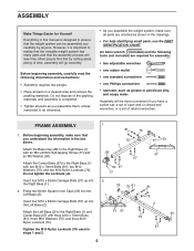
...; one Phillips screwdriver • lubricant, such as shown in the drawings. • For help identifying small parts, use the PART IDENTIFICATION CHART. Most people find that by setting aside plenty of the packing materials until assembly is completed. • Tighten all parts as you assemble them, unless instructed to the Right Base (1) with three M10 x 70mm Bolts (81), three M10 Washers (75...
...; one Phillips screwdriver • lubricant, such as shown in the drawings. • For help identifying small parts, use the PART IDENTIFICATION CHART. Most people find that by setting aside plenty of the packing materials until assembly is completed. • Tighten all parts as you assemble them, unless instructed to the Right Base (1) with three M10 x 70mm Bolts (81), three M10 Washers (75...
English Manual
Page 9
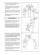
...Large Foam Pad (19) onto the Arm. Press a 25mm Round Inner Cap (24) into the end of the M10 Nylon Locknuts (70) used in steps 3-11. 11 70 44 70 14 81 75 70 8 70 75 81 75 20 3 ARM ASSEMBLY 12 8 12. Attach the Handle to the Right Top Frame...grease. Repeat this step with the bottom of the Arm with two M10 x 70mm Bolts (81), two M10 Washers (75), and two M10 Nylon Locknuts (70). Slide a Foam Grip (76) onto a Press Handle (12). Press the two Weight Guide Bushings (44) into the indicated end of the Foam Pad is even with the Left Butterfly Arm (10). 13 Lubricate...
...Large Foam Pad (19) onto the Arm. Press a 25mm Round Inner Cap (24) into the end of the M10 Nylon Locknuts (70) used in steps 3-11. 11 70 44 70 14 81 75 70 8 70 75 81 75 20 3 ARM ASSEMBLY 12 8 12. Attach the Handle to the Right Top Frame...grease. Repeat this step with the bottom of the Arm with two M10 x 70mm Bolts (81), two M10 Washers (75), and two M10 Nylon Locknuts (70). Slide a Foam Grip (76) onto a Press Handle (12). Press the two Weight Guide Bushings (44) into the indicated end of the Foam Pad is even with the Left Butterfly Arm (10). 13 Lubricate...
English Manual
Page 10
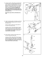
...able to pivot easily. 16. Lubricate Repeat this step with grease. Do not overtighten the Locknut; 14. Do not overtighten the Locknut; Press two 40mm x 50mm Inner Caps (23) into the 16 top of the Leg Lever (4). Lubricate an M10 x 80mm Bolt (61) with the Left Butterfly Arm 70 9 10 (10). 15... and an M10 11 Nylon Locknut (70). Lubricate an M10 x 80mm Button Head Bolt (97) and both sides of the 55 Plastic Washers fit over the welded bushing in 54 the Butterfly Arm. Attach the Right Butterfly Arm (11) to pivot easily. 73 23 Lubricate 70 63 77 25 50 4 23 22...
...able to pivot easily. 16. Lubricate Repeat this step with grease. Do not overtighten the Locknut; 14. Do not overtighten the Locknut; Press two 40mm x 50mm Inner Caps (23) into the 16 top of the Leg Lever (4). Lubricate an M10 x 80mm Bolt (61) with the Left Butterfly Arm 70 9 10 (10). 15... and an M10 11 Nylon Locknut (70). Lubricate an M10 x 80mm Button Head Bolt (97) and both sides of the 55 Plastic Washers fit over the welded bushing in 54 the Butterfly Arm. Attach the Right Butterfly Arm (11) to pivot easily. 73 23 Lubricate 70 63 77 25 50 4 23 22...

English Manual
Page 11
... the weight system, with an M10 x 45mm Bolt (66) and an M10 Nylon Locknut (70). 70 14 38 45 66 11 Locate the High Cable (45). Be sure the Cable Trap is completed. 19. CABLE ASSEMBLY 17. Refer to the CABLE DIAGRAMS and the CABLE ID CHART on the Center Top Frame (14) with the Left Top Frame (3) removed for proper cable routing. Attach the Pulley...
... the weight system, with an M10 x 45mm Bolt (66) and an M10 Nylon Locknut (70). 70 14 38 45 66 11 Locate the High Cable (45). Be sure the Cable Trap is completed. 19. CABLE ASSEMBLY 17. Refer to the CABLE DIAGRAMS and the CABLE ID CHART on the Center Top Frame (14) with the Left Top Frame (3) removed for proper cable routing. Attach the Pulley...
English Manual
Page 13
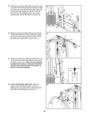
... Leg Press Cable (95) around a 90mm Pulley (38). it should be threaded only two turns onto the end of the Leg Press Cable (95) to the Pivot Bracket (48) on the Left Top Frame (3) with an M8 x 16mm Shoulder Bolt (78) and an M8 Nylon Locknut (71). 71 46 48 78 10 13 Locate the Butterfly Cable (46). Attach the Pulley inside the Upright...
... Leg Press Cable (95) around a 90mm Pulley (38). it should be threaded only two turns onto the end of the Leg Press Cable (95) to the Pivot Bracket (48) on the Left Top Frame (3) with an M8 x 16mm Shoulder Bolt (78) and an M8 Nylon Locknut (71). 71 46 48 78 10 13 Locate the Butterfly Cable (46). Attach the Pulley inside the Upright...
English Manual
Page 16
...75 81 7 47 36 40. 37. Be sure the Cable Trap is turned to hold the Cable in the groove of the Leg Lever Cable (96) to the lower set of the Cable, as shown in the indicated "U"-Bracket (85) with an M10 x 70mm Bolt (81), two M10 Washers (75), two 13mm Spacers (... 75 Cage 47 39. Route the small ball 38 on the Leg Press Frame (30). Note: Do not completely tighten the Nylon Locknut; Wrap the Low Cable (47) around a 90mm Pulley 40 (38). Locate the Low Cable (47). Attach a 90mm Pulley (38) inside the Leg Press Frame (30) with an M10 x 50mm Bolt (62) and an M10...
...75 81 7 47 36 40. 37. Be sure the Cable Trap is turned to hold the Cable in the groove of the Leg Lever Cable (96) to the lower set of the Cable, as shown in the indicated "U"-Bracket (85) with an M10 x 70mm Bolt (81), two M10 Washers (75), two 13mm Spacers (... 75 Cage 47 39. Route the small ball 38 on the Leg Press Frame (30). Note: Do not completely tighten the Nylon Locknut; Wrap the Low Cable (47) around a 90mm Pulley 40 (38). Locate the Low Cable (47). Attach a 90mm Pulley (38) inside the Leg Press Frame (30) with an M10 x 50mm Bolt (62) and an M10...
English Manual
Page 19
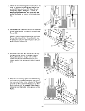
...Adjustable Backrest Frame (101). Attach the Leg Press Plate (31) to an Adjustable Seat Frame (100) with two M6 x 16mm Screws (13), an M6 x 33mm Screw (90), and an M6 Washer (35). Press two 20mm x 40mm Inner Caps (104) and a 25mm x 40mm Inner Cap (105) into the indicated end of the Pad Tube. Attach a Seat... Pad Tube (94) and the Leg Lever (4). 52. SEAT ASSEMBLY 49. Repeat this step with an Adjustment Knob (102). Attach a Backrest (15) to the Leg Press Frame (30) with the other Backrest (15) and the Left Upright (not shown) with an Adjustment Knob (102). Slide the Long Pad ...
...Adjustable Backrest Frame (101). Attach the Leg Press Plate (31) to an Adjustable Seat Frame (100) with two M6 x 16mm Screws (13), an M6 x 33mm Screw (90), and an M6 Washer (35). Press two 20mm x 40mm Inner Caps (104) and a 25mm x 40mm Inner Cap (105) into the indicated end of the Pad Tube. Attach a Seat... Pad Tube (94) and the Leg Lever (4). 52. SEAT ASSEMBLY 49. Repeat this step with an Adjustment Knob (102). Attach a Backrest (15) to the Leg Press Frame (30) with the other Backrest (15) and the Left Upright (not shown) with an Adjustment Knob (102). Slide the Long Pad ...
English Manual
Page 20
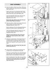
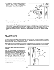
... cleaned with two Cable Clips. Replace any slack in ADJUSTMENTS, starting position for each time the weight system is any worn parts immediately. Attach the tether on page 26 for proper cable routing. ADJUSTMENTS This section explains how to get the most benefit from your exercise program. Do not use of the cables does not move smoothly over the pulleys. Insert the two Locking Pins (53) into...
... cleaned with two Cable Clips. Replace any slack in ADJUSTMENTS, starting position for each time the weight system is any worn parts immediately. Attach the tether on page 26 for proper cable routing. ADJUSTMENTS This section explains how to get the most benefit from your exercise program. Do not use of the cables does not move smoothly over the pulleys. Insert the two Locking Pins (53) into...
English Manual
Page 21
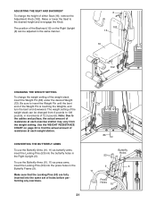
... press arms, insert the Locking Pins (53) into the press holes in the Right Upright (6). The position of the Backrest (15) on page 23 to 106 pounds, in the same manner. 6 102 15 16 102 CHANGING THE WEIGHT SETTING To change the height of either Seat (16), remove the Adjustment Knob (102). Note: Due to the cables and pulleys, the actual amount of resistance at each exercise...
... press arms, insert the Locking Pins (53) into the press holes in the Right Upright (6). The position of the Backrest (15) on page 23 to 106 pounds, in the same manner. 6 102 15 16 102 CHANGING THE WEIGHT SETTING To change the height of either Seat (16), remove the Adjustment Knob (102). Note: Due to the cables and pulleys, the actual amount of resistance at each exercise...
English Manual
Page 22
...Weight (74) will be removed by tightening the M8 Nylon Locknuts (71) attaching a cable to a higher set of holes in the Adjustable Double "U"-Bracket with the Bolt and Locknut. To do this, you may need to the locked position around the Leg Press Frame. Slack can also be tightened. See drawing A. Re-attach the Pulley and the Cable... same manner. Slack can be lifted off the weight stack. ADJUSTING THE LEG PRESS PLATE To adjust the Leg Press Plate (31), remove the Leg Press Pin (87) from the cables by moving the 90mm Pulley (38) and Cable Trap (91) to either "U"-Bracket (85), ...
...Weight (74) will be removed by tightening the M8 Nylon Locknuts (71) attaching a cable to a higher set of holes in the Adjustable Double "U"-Bracket with the Bolt and Locknut. To do this, you may need to the locked position around the Leg Press Frame. Slack can also be tightened. See drawing A. Re-attach the Pulley and the Cable... same manner. Slack can be lifted off the weight stack. ADJUSTING THE LEG PRESS PLATE To adjust the Leg Press Plate (31), remove the Leg Press Pin (87) from the cables by moving the 90mm Pulley (38) and Cable Trap (91) to either "U"-Bracket (85), ...
English Manual
Page 23
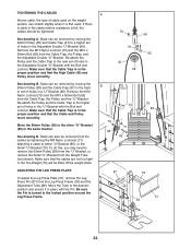
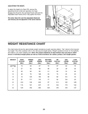
... to the 12.5-pound weight plates. Note: The actual resistance at each butterfly arm. The other numbers refer to the 6-pound top weight. ADJUSTING THE SEATS to differences in the same manner. 16 100 29 102 WEIGHT RESISTANCE CHART The chart below shows the approximate weight resistance at each station may vary due to adjust the height of a Seat (16), remove the Adjustment Knob (102) and reposition the...
... to the 12.5-pound weight plates. Note: The actual resistance at each butterfly arm. The other numbers refer to the 6-pound top weight. ADJUSTING THE SEATS to differences in the same manner. 16 100 29 102 WEIGHT RESISTANCE CHART The chart below shows the approximate weight resistance at each station may vary due to adjust the height of a Seat (16), remove the Adjustment Knob (102) and reposition the...
English Manual
Page 24
... Cable (45) 6 6 11 Low Cable (47) 7 9 8 10 3 5 4 2 1 24 The numbers show the proper routing of the High Cable (45), the Butterfly Cable (46), the Low Cable (47), the Leg Press Cable (95), and the Leg Lever Cable (96). If the cables have been assembled correctly. CABLE DIAGRAMS The cable diagrams below show the correct route for each cable. Make sure that the cables and the cable traps have not been correctly routed, the weight...
... Cable (45) 6 6 11 Low Cable (47) 7 9 8 10 3 5 4 2 1 24 The numbers show the proper routing of the High Cable (45), the Butterfly Cable (46), the Low Cable (47), the Leg Press Cable (95), and the Leg Lever Cable (96). If the cables have been assembled correctly. CABLE DIAGRAMS The cable diagrams below show the correct route for each cable. Make sure that the cables and the cable traps have not been correctly routed, the weight...
English Manual
Page 26
formed. (A "repetition" is a series of repetitions.) The proper amount of weight for 3 minutes after each set . Rest for each set . Exercise for a maximum of 30 seconds between sets. Cross Training Cross training is important to a moderate percentage of their maximum capacity. The combination of weight training and aerobic exercise will continually adapt and grow as possible without discomfort. It is an efficient way to 30 minutes, resting...
formed. (A "repetition" is a series of repetitions.) The proper amount of weight for 3 minutes after each set . Rest for each set . Exercise for a maximum of 30 seconds between sets. Cross Training Cross training is important to a moderate percentage of their maximum capacity. The combination of weight training and aerobic exercise will continually adapt and grow as possible without discomfort. It is an efficient way to 30 minutes, resting...

English Manual
Page 27
... as you can without strain. list the date, the exercises performed, the weight used, and the numbers of leg) W. Pectoralis Major (chest) A C. Trapezius (upper back) H O. Gluteus Maximus (buttocks) V. Rest for a short period of time after each set for a toning work- The ideal resting periods are: • Rest for three minutes after each set for a muscle building workout. • Rest for one...
... as you can without strain. list the date, the exercises performed, the weight used, and the numbers of leg) W. Pectoralis Major (chest) A C. Trapezius (upper back) H O. Gluteus Maximus (buttocks) V. Rest for a short period of time after each set for a toning work- The ideal resting periods are: • Rest for three minutes after each set for a muscle building workout. • Rest for one...

English Manual
Page 30
...-tapping Screw M8 x 16mm Shoulder Bolt Small "U"-Bracket Long Spacer M10 x 70mm Bolt Weight Tube Weight Bumper M10 x 100mm Bolt "U"-Bracket Weight Pin Leg Press Pin Adjustment Tube M8 x 65mm Bolt M6 x 33mm Screw Cable Trap Pulley Cover Ab Strap Short Pad Tube Leg Press Cable Leg Lever Cable M10 x 80mm Button Head Bolt M10 x 95mm Bolt M10 x 25mm Shoulder Bolt Seat Frame Backrest Frame Adjustment Knob Double "U"-Bracket 20mm x 40mm Inner Cap 25mm x 40mm Inner Cap User's Manual Exercise Guide Allen Wrench Grease Packet...
...-tapping Screw M8 x 16mm Shoulder Bolt Small "U"-Bracket Long Spacer M10 x 70mm Bolt Weight Tube Weight Bumper M10 x 100mm Bolt "U"-Bracket Weight Pin Leg Press Pin Adjustment Tube M8 x 65mm Bolt M6 x 33mm Screw Cable Trap Pulley Cover Ab Strap Short Pad Tube Leg Press Cable Leg Lever Cable M10 x 80mm Button Head Bolt M10 x 95mm Bolt M10 x 25mm Shoulder Bolt Seat Frame Backrest Frame Adjustment Knob Double "U"-Bracket 20mm x 40mm Inner Cap 25mm x 40mm Inner Cap User's Manual Exercise Guide Allen Wrench Grease Packet...

English Manual
Page 32
... following information: 1. The SERIAL NUMBER of the product (see the PART LIST in the center of this manual) LIMITED WARRANTY ICON Health & Fitness, Inc. (ICON), warrants this product to be free from defects in connection with respect to any implied warranties of merchantability or fitness for indirect, special or consequential damages arising out of whatsoever nature. No other warranty beyond that specifically set forth herein. ICON's obligation under normal use and service...
... following information: 1. The SERIAL NUMBER of the product (see the PART LIST in the center of this manual) LIMITED WARRANTY ICON Health & Fitness, Inc. (ICON), warrants this product to be free from defects in connection with respect to any implied warranties of merchantability or fitness for indirect, special or consequential damages arising out of whatsoever nature. No other warranty beyond that specifically set forth herein. ICON's obligation under normal use and service...


