
English Manual
Page 2
TABLE OF CONTENTS IMPORTANT PRECAUTIONS 3 BEFORE YOU BEGIN 4 ASSEMBLY 5 ADJUSTMENTS 20 WEIGHT RESISTANCE CHART 23 CABLE DIAGRAM 24 EXERCISE GUIDELINES 26 ORDERING REPLACEMENT PARTS Back Cover FULL 90 DAY WARRANTY Back Cover Note: A PART IDENTIFICATION CHART and a PART LIST/EXPLODED DRAWING are attached in the center of ICON Health & Fitness, Inc. 2 Remove the PART IDENTIFICATION CHART and the PART LIST/EXPLODED DRAWING before beginning assembly. WEIDER is a registered trademark of this manual.
TABLE OF CONTENTS IMPORTANT PRECAUTIONS 3 BEFORE YOU BEGIN 4 ASSEMBLY 5 ADJUSTMENTS 20 WEIGHT RESISTANCE CHART 23 CABLE DIAGRAM 24 EXERCISE GUIDELINES 26 ORDERING REPLACEMENT PARTS Back Cover FULL 90 DAY WARRANTY Back Cover Note: A PART IDENTIFICATION CHART and a PART LIST/EXPLODED DRAWING are attached in the center of ICON Health & Fitness, Inc. 2 Remove the PART IDENTIFICATION CHART and the PART LIST/EXPLODED DRAWING before beginning assembly. WEIDER is a registered trademark of this manual.

English Manual
Page 4
For your cardiovascular system, the weight system will help us assist you for selecting the versatile WEIDER® PRO 3200 weight system. Butterfly Arm Press Arm Ab Pulley Station Warning Decal 2 (One on a decal attached to right and left side" ... benefit, read this manual, please call our Customer Service Department toll-free at 1-800-999-3756, Monday through Friday, 6 a.m. ASSEMBLED DIMENSIONS: Height: 77 in the manual. The PRO 3200 weight system offers a selection of weight stations designed to a person facing away from the weight system; until 6 p.m. Before reading ...
For your cardiovascular system, the weight system will help us assist you for selecting the versatile WEIDER® PRO 3200 weight system. Butterfly Arm Press Arm Ab Pulley Station Warning Decal 2 (One on a decal attached to right and left side" ... benefit, read this manual, please call our Customer Service Department toll-free at 1-800-999-3756, Monday through Friday, 6 a.m. ASSEMBLED DIMENSIONS: Height: 77 in the manual. The PRO 3200 weight system offers a selection of weight stations designed to a person facing away from the weight system; until 6 p.m. Before reading ...
English Manual
Page 5
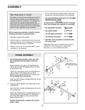
... the versatile weight system has many parts and that by anyone. An Allen wrench (included) and the following information and instructions: • Assembly requires two people. • Place all parts in the drawings. • For help identifying small parts, use the PART IDENTIFICATION CHART. ...M10 x 70mm Bolts (81), three M10 Washers (75), and three M10 Nylon Locknuts (70). Do not tighten the Locknuts yet. Before beginning assembly, carefully read the following tools (not included) are oriented as shown in a cleared area and remove the packing materials. Attach the Base Cap...
... the versatile weight system has many parts and that by anyone. An Allen wrench (included) and the following information and instructions: • Assembly requires two people. • Place all parts in the drawings. • For help identifying small parts, use the PART IDENTIFICATION CHART. ...M10 x 70mm Bolts (81), three M10 Washers (75), and three M10 Nylon Locknuts (70). Do not tighten the Locknuts yet. Before beginning assembly, carefully read the following tools (not included) are oriented as shown in a cleared area and remove the packing materials. Attach the Base Cap...
English Manual
Page 9
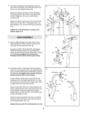
... all of the M10 Nylon Locknuts (70) used in steps 3-11. 11 70 44 70 14 81 75 70 8 70 75 81 75 20 3 ARM ASSEMBLY 12 8 12. Press a 50mm x 70mm Inner Cap (22) into the Right Upright (6). Slide a Large Foam Pad (19) onto the Arm. 11. Press the two Weight...
... all of the M10 Nylon Locknuts (70) used in steps 3-11. 11 70 44 70 14 81 75 70 8 70 75 81 75 20 3 ARM ASSEMBLY 12 8 12. Press a 50mm x 70mm Inner Cap (22) into the Right Upright (6). Slide a Large Foam Pad (19) onto the Arm. 11. Press the two Weight...

English Manual
Page 11
IMPORTANT: While assembling the cables, do not overtighten the locknuts attaching the pulleys; the pulleys must be necessary to loosen the indicated M10 Nylon Locknuts (70). Route the .... Attach the Pulley to hold the Cable in the groove of the weight system, with the Left Top Frame (3) removed for proper cable routing. CABLE ASSEMBLY 17. Attach the Pulley and a Cable Trap (91) inside of the Adjustable Double "U"-Bracket (56) with an M10 x 70mm Bolt (81), two M10 Washers (75...
IMPORTANT: While assembling the cables, do not overtighten the locknuts attaching the pulleys; the pulleys must be necessary to loosen the indicated M10 Nylon Locknuts (70). Route the .... Attach the Pulley to hold the Cable in the groove of the weight system, with the Left Top Frame (3) removed for proper cable routing. CABLE ASSEMBLY 17. Attach the Pulley and a Cable Trap (91) inside of the Adjustable Double "U"-Bracket (56) with an M10 x 70mm Bolt (81), two M10 Washers (75...
English Manual
Page 19
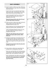
... (30) with the Short Pad Tube (94) and the Leg Lever (4). 52. Slide two Foam Pads (18) onto the ends of the Pad Tube. SEAT ASSEMBLY 49. Press two 20mm x 40mm Inner Caps (104) and a 25mm x 40mm Inner Cap (105) into the ends of the Pad Tube. Insert the Adjustable Backrest...
... (30) with the Short Pad Tube (94) and the Leg Lever (4). 52. Slide two Foam Pads (18) onto the ends of the Pad Tube. SEAT ASSEMBLY 49. Press two 20mm x 40mm Inner Caps (104) and a 25mm x 40mm Inner Cap (105) into the ends of the Pad Tube. Insert the Adjustable Backrest...
English Manual
Page 24
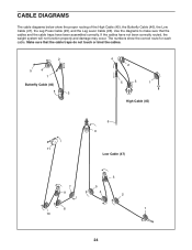
If the cables have been assembled correctly. CABLE DIAGRAMS The cable diagrams below show the correct route for each cable. Make sure that the cables and the cable traps have not ...
If the cables have been assembled correctly. CABLE DIAGRAMS The cable diagrams below show the correct route for each cable. Make sure that the cables and the cable traps have not ...


