
Uk Manual
Page 1
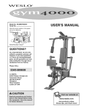
... serial number in this manual before using this manual for reference. USERʼS MANUAL Visit our website at www.weslo.com new products, prizes, fitness tips, and much more! As a manufacturer, we will guarantee you have questions, or if there are missing/damaged parts, we are committed to complete customer satisfaction. Model No. Serial Number Decal QUESTIONS? If you complete satisfaction through direct...
... serial number in this manual before using this manual for reference. USERʼS MANUAL Visit our website at www.weslo.com new products, prizes, fitness tips, and much more! As a manufacturer, we will guarantee you have questions, or if there are missing/damaged parts, we are committed to complete customer satisfaction. Model No. Serial Number Decal QUESTIONS? If you complete satisfaction through direct...
Uk Manual
Page 2
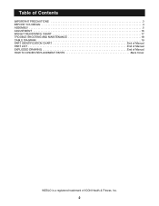
Table of Contents IMPORTANT PRECAUTIONS 3 BEFORE YOU BEGIN 4 ASSEMBLY 5 ADJUSTMENT 16 WEIGHT RESISTANCE CHART 17 TROUBLE-SHOOTING AND MAINTENANCE 18 CABLE DIAGRAM 19 PART IDENTIFICATION CHART End of Manual PART LIST End of Manual EXPLODED DRAWING End of Manual HOW TO ORDER REPLACEMENT PARTS Back Cover WESLO is a registered trademark of ICON Health & Fitness, Inc. 2
Table of Contents IMPORTANT PRECAUTIONS 3 BEFORE YOU BEGIN 4 ASSEMBLY 5 ADJUSTMENT 16 WEIGHT RESISTANCE CHART 17 TROUBLE-SHOOTING AND MAINTENANCE 18 CABLE DIAGRAM 19 PART IDENTIFICATION CHART End of Manual PART LIST End of Manual EXPLODED DRAWING End of Manual HOW TO ORDER REPLACEMENT PARTS Back Cover WESLO is a registered trademark of ICON Health & Fitness, Inc. 2
Uk Manual
Page 3
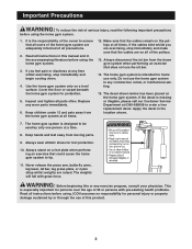
... parts often. Never release the press arm, butterfly arms, leg lever, lat bar, leg press plate, or nylon strap whilst weights are on a level surface. This is the responsibility of this or any worn parts immediately. 6. Cover the floor or carpet beneath the home gym system for persons over the age of the pulleys. 13. Do not use the lat bar. 14. Apply the decal in any time whilst exercising, stop...
... parts often. Never release the press arm, butterfly arms, leg lever, lat bar, leg press plate, or nylon strap whilst weights are on a level surface. This is the responsibility of this or any worn parts immediately. 6. Cover the floor or carpet beneath the home gym system for persons over the age of the pulleys. 13. Do not use the lat bar. 14. Apply the decal in any time whilst exercising, stop...
Uk Manual
Page 4
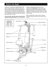
... home gym system. The model number is to the home gym system (see the front cover of the body. The serial number can be found on a decal attached to tone your body, build dramatic muscle size and strength, or improve your benefit, read this manual). ASSEMBLED DIMENSIONS: Height: 193 cm Width: 97 cm Length: 150 cm Lat Bar Holder High Pulley Station Lat Bar Butterfly Arms Backrest Leg Press Plate Leg Lever Low Pulley Station Press Arm Seat Weight Stack Weight Pin...
... home gym system. The model number is to the home gym system (see the front cover of the body. The serial number can be found on a decal attached to tone your body, build dramatic muscle size and strength, or improve your benefit, read this manual). ASSEMBLED DIMENSIONS: Height: 193 cm Width: 97 cm Length: 150 cm Lat Bar Holder High Pulley Station Lat Bar Butterfly Arms Backrest Leg Press Plate Leg Lever Low Pulley Station Press Arm Seat Weight Stack Weight Pin...
Uk Manual
Page 5
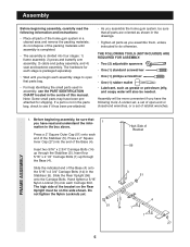
Before beginning assembly, be on the Rear Upright must be sure that you have been preattached for each assembly stage to open -end or closed-end wrenches, or a set of open that parts bag. • For help identifying the small parts used in assembly, use the PART IDENTIFICATION CHART located in the centre of this manual. Insert four 5/16" x 2 1/2" Carriage Bolts (1) up through the Base (4). Slide the indicated...
Before beginning assembly, be on the Rear Upright must be sure that you have been preattached for each assembly stage to open -end or closed-end wrenches, or a set of open that parts bag. • For help identifying the small parts used in assembly, use the PART IDENTIFICATION CHART located in the centre of this manual. Insert four 5/16" x 2 1/2" Carriage Bolts (1) up through the Base (4). Slide the indicated...
Uk Manual
Page 6
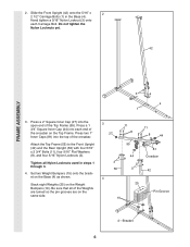
... Pin Groove 19 4-Bracket 6 2. Attach the Top Frame (55) to the Front Upright (42) and the Rear Upright (56) with four 5/16" x 2 3/4" Bolts (11), four 5/16" Flat Washers (8), and four 5/16" Nylon Locknuts (3). Slide the Front Upright (42) onto the 5/16" x 2 2 1/2" Carriage Bolts (1) in steps 1 through 3. 4. Stack eight Weights (25) on the Top Frame. Press a 1 3/4" Square Inner Cap (44) into the open...
... Pin Groove 19 4-Bracket 6 2. Attach the Top Frame (55) to the Front Upright (42) and the Rear Upright (56) with four 5/16" x 2 3/4" Bolts (11), four 5/16" Flat Washers (8), and four 5/16" Nylon Locknuts (3). Slide the Front Upright (42) onto the 5/16" x 2 2 1/2" Carriage Bolts (1) in steps 1 through 3. 4. Stack eight Weights (25) on the Top Frame. Press a 1 3/4" Square Inner Cap (44) into the open...
Uk Manual
Page 8
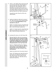
... lower end of the Right Arm is very important for step 10. Note the position of the Press Frame (17) with a 3/8" x 2 1/2" Bolt (7) and a 3/8" Nylon Locknut (21). Attach a "V"-Pulley (6) and a Long Cable Trap (50) to confuse the Right Arm with a 3/8" x 2 1/2" Bolt (7) and a 3/8" Nylon Locknut (21). 8 31 44 49 46 22 9 50 6 Welded Brackets 48 3 17 7 50 6 21 44 49 46 47 ARM ASSEMBLY...
... lower end of the Right Arm is very important for step 10. Note the position of the Press Frame (17) with a 3/8" x 2 1/2" Bolt (7) and a 3/8" Nylon Locknut (21). Attach a "V"-Pulley (6) and a Long Cable Trap (50) to confuse the Right Arm with a 3/8" x 2 1/2" Bolt (7) and a 3/8" Nylon Locknut (21). 8 31 44 49 46 22 9 50 6 Welded Brackets 48 3 17 7 50 6 21 44 49 46 47 ARM ASSEMBLY...
Uk Manual
Page 9
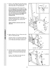
... Leg Lever (29) to the Front Upright (42) with the 3/8" x 3 1/4" Bolt and a 3/8" Nylon Locknut (21). 4 1 73 65 32 21 13. Slide the Seat Frame (36) onto the 5/16" x 2 1/2" Carriage Bolts (1) in this assembly step. 3 Attach the Seat Frame (36) to the Rocker Arm (32) with a 1/2" Tap Screw (65). 12 Lubricate a 3/8" x 3 1/4" Bolt (35). The bracket on the Seat Frame must be behind the Press Frame (17). Lubricate a 3/8" x 2 1/2" Bolt...
... Leg Lever (29) to the Front Upright (42) with the 3/8" x 3 1/4" Bolt and a 3/8" Nylon Locknut (21). 4 1 73 65 32 21 13. Slide the Seat Frame (36) onto the 5/16" x 2 1/2" Carriage Bolts (1) in this assembly step. 3 Attach the Seat Frame (36) to the Rocker Arm (32) with a 1/2" Tap Screw (65). 12 Lubricate a 3/8" x 3 1/4" Bolt (35). The bracket on the Seat Frame must be behind the Press Frame (17). Lubricate a 3/8" x 2 1/2" Bolt...
Uk Manual
Page 10
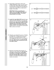
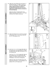
... the hook. Be sure that the Cable is in the groove of the Pulley and that the Long Cable Trap (50) is positioned to the CABLE DIAGRAM on the Left Arm (47). During steps 15 through 29, refer to hold the Cable in place. 17. Locate the Long Cable (23). Route the Long Cable around a "V"-Pulley (6). Tighten the 3/8" x 3 3/4" Bolt (71) and the 3/8" Nylon Locknut (not...
... the hook. Be sure that the Cable is in the groove of the Pulley and that the Long Cable Trap (50) is positioned to the CABLE DIAGRAM on the Left Arm (47). During steps 15 through 29, refer to hold the Cable in place. 17. Locate the Long Cable (23). Route the Long Cable around a "V"-Pulley (6). Tighten the 3/8" x 3 3/4" Bolt (71) and the 3/8" Nylon Locknut (not...
Uk Manual
Page 11
... removed for easy part identification. 23 15 Bracket 12 Route the Long Cable (23) around the 3 1/2" Pulley (15) attached to the indicated 20 hole in this 21 step is turned to the bracket on the Right Arm (48). Bracket. Note: The 3 1/2" Pulley (15) labelled in the Long "U"-Bracket (57) with a 3/8" x 2" Bolt (12) and a 3/8" Nylon Locknut (21). Be sure that the Cable and Pulley move...
... removed for easy part identification. 23 15 Bracket 12 Route the Long Cable (23) around the 3 1/2" Pulley (15) attached to the indicated 20 hole in this 21 step is turned to the bracket on the Right Arm (48). Bracket. Note: The 3 1/2" Pulley (15) labelled in the Long "U"-Bracket (57) with a 3/8" x 2" Bolt (12) and a 3/8" Nylon Locknut (21). Be sure that the Cable and Pulley move...
Uk Manual
Page 12
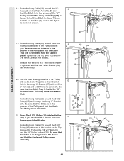
...) is turned to the Rocker Arm (32) with a 3/8" x 2 1/2" Bolt (7) and a 3/8" Nylon Locknut (21). Route the 22 Short Cable under the 3 1/2" Low Pulley (77). Attach the Pulley and a Long 23 Cable Trap (50) inside the bracket on the indicated side of the Pulley and that the Cable is pre-attached. CABLE ASSEMBLY 22. Wrap the Short Cable (58) around a 3 1/2" Pulley (15). Locate the Short Cable (58). Note: The 3 1/2" Pulley (15...
...) is turned to the Rocker Arm (32) with a 3/8" x 2 1/2" Bolt (7) and a 3/8" Nylon Locknut (21). Route the 22 Short Cable under the 3 1/2" Low Pulley (77). Attach the Pulley and a Long 23 Cable Trap (50) inside the bracket on the indicated side of the Pulley and that the Cable is pre-attached. CABLE ASSEMBLY 22. Wrap the Short Cable (58) around a 3 1/2" Pulley (15). Locate the Short Cable (58). Note: The 3 1/2" Pulley (15...
Uk Manual
Page 13
... 58 15 21 66 28. Route the Short Cable (58) around the 3 1/2" Pulley (15) attached to hold the Cable in place and that the Cable Trap (66) is turned to the upper hole in this step is pre-attached. Tighten the 3/8" Nylon Locknut (21) and the 3/8" x 3 1/2" Bolt (16). 27. It is shown removed for easy part identification. Note: The 3 1/2" Pulley (15) labelled in the...
... 58 15 21 66 28. Route the Short Cable (58) around the 3 1/2" Pulley (15) attached to hold the Cable in place and that the Cable Trap (66) is turned to the upper hole in this step is pre-attached. Tighten the 3/8" Nylon Locknut (21) and the 3/8" x 3 1/2" Bolt (16). 27. It is shown removed for easy part identification. Note: The 3 1/2" Pulley (15) labelled in the...
Uk Manual
Page 14
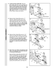
... the 1/4" x 2 1/2" Carriage Bolt (38) into the centre hole in the Seat Plate (37). Do not com- Attach 31 the Seat Plate to the Weight Tube (63) with two 1/4" x 3/4" Screws (18). Attach the other end of turns, as shown in the Seat Frame (36). pletely tighten the Nylon Locknut. Tighten a 1/4" Nylon Locknut (2) with a 1/4" Nylon Locknut (2) and a 1/4" Flat Washer (10). CABLE ASSEMBLY 29. It should...
... the 1/4" x 2 1/2" Carriage Bolt (38) into the centre hole in the Seat Plate (37). Do not com- Attach 31 the Seat Plate to the Weight Tube (63) with two 1/4" x 3/4" Screws (18). Attach the other end of turns, as shown in the Seat Frame (36). pletely tighten the Nylon Locknut. Tighten a 1/4" Nylon Locknut (2) with a 1/4" Nylon Locknut (2) and a 1/4" Flat Washer (10). CABLE ASSEMBLY 29. It should...
Uk Manual
Page 15
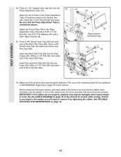
... parts will need to the Press Adjustment Tube (79) with the holes in ADJUSTMENT, beginning on page 16 of the Long Pad Tube (80). Before using the home gym system, pull each end of the Long Pad Tube. 32 44 79 8 3 8 22 40 32 78 Slant must be sure that the cables move smoothly, find and correct the problem. SEAT ASSEMBLY 32. Attach the Press...
... parts will need to the Press Adjustment Tube (79) with the holes in ADJUSTMENT, beginning on page 16 of the Long Pad Tube (80). Before using the home gym system, pull each end of the Long Pad Tube. 32 44 79 8 3 8 22 40 32 78 Slant must be sure that the cables move smoothly, find and correct the problem. SEAT ASSEMBLY 32. Attach the Press...
Uk Manual
Page 16
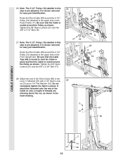
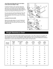
...). Use the WEIGHT RESISTANCE CHART on page 17). For some exercises, the Chain (52) should be attached between the Lat Bar and the Short Cable so the Lat Bar is any slack in the correct starting position for the exercise to the cables and pulleys, the amount of the weight stack, insert a Weight Pin (26) under the desired Weight (25). The Nylon Strap (39) can be performed. Always remove the leg press plate...
...). Use the WEIGHT RESISTANCE CHART on page 17). For some exercises, the Chain (52) should be attached between the Lat Bar and the Short Cable so the Lat Bar is any slack in the correct starting position for the exercise to the cables and pulleys, the amount of the weight stack, insert a Weight Pin (26) under the desired Weight (25). The Nylon Strap (39) can be performed. Always remove the leg press plate...
Uk Manual
Page 17
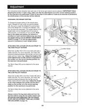
...). Align a different set of holes in the Press Adjustment Tube with the set of the Leg Press Plate (78), remove the "L"-Pin (40) from the Press Adjustment Tube (79) and the Rocker Arm (32). Weight resistance shown for the butterfly arm station is in use, the Leg Lever (29) must be locked in individual weight plates, as well as friction between the cables, pulleys, and weight guides. Insert the "L"-Pin (40) through...
...). Align a different set of holes in the Press Adjustment Tube with the set of the Leg Press Plate (78), remove the "L"-Pin (40) from the Press Adjustment Tube (79) and the Rocker Arm (32). Weight resistance shown for the butterfly arm station is in use, the Leg Lever (29) must be locked in individual weight plates, as well as friction between the cables, pulleys, and weight guides. Insert the "L"-Pin (40) through...
Uk Manual
Page 18
... home gym system, can be cleaned using a damp cloth and mild non-abrasive detergent. Re-attach the Pulley and Cable Trap. The home gym system can stretch slightly when it . If the cables need to be tightened. Trouble-shooting and Maintenance Inspect and tighten all parts each time you may have become twisted. To do this manual. 66 57 21 12 2 58 18 Remove the cable and re-install...
... home gym system, can be cleaned using a damp cloth and mild non-abrasive detergent. Re-attach the Pulley and Cable Trap. The home gym system can stretch slightly when it . If the cables need to be tightened. Trouble-shooting and Maintenance Inspect and tighten all parts each time you may have become twisted. To do this manual. 66 57 21 12 2 58 18 Remove the cable and re-install...
Uk Manual
Page 19
... touch or bind the cables. Long Cable (23) 2 1-High Pulley 7 3 5 4 6 7-Long "U"-Bracket Short Cable (58) Weight Stack-8 6 5 2 1-Low Pulley 4 3 19 If the cables have been assembled correctly. Cable Diagram The cable diagram below shows the proper routing of each cable. The numbers show the correct route for each cable are labelled. Be sure that the two cables and the cable traps have not been correctly routed, the home gym system will not...
... touch or bind the cables. Long Cable (23) 2 1-High Pulley 7 3 5 4 6 7-Long "U"-Bracket Short Cable (58) Weight Stack-8 6 5 2 1-Low Pulley 4 3 19 If the cables have been assembled correctly. Cable Diagram The cable diagram below shows the proper routing of each cable. The numbers show the correct route for each cable are labelled. Be sure that the two cables and the cable traps have not been correctly routed, the home gym system will not...
Uk Manual
Page 23
... 1 Lat Bar 55 1 Top Frame 56 1 Rear Upright 57 1 Long "U"-Bracket 58 1 Short Cable 59 1 3/8" x 8" Bolt 60 1 5/16" x 6" Bolt 61 2 1/2" x 3/4" Spacer 62 2 Weight Guide 63 1 Weight Tube 64 1 Weight Tube Bumper 65 2 #8 x 3/4" Tap Screw 66 6 Cable Trap 67 1 Small "U"-Bracket 68 1 5/16" x 5" Bolt 69 4 1" Retainer 70 2 1" Round Cover Cap 71 3 3/8" x 3 3/4" Bolt 72 1 5/16" x 1 3/4" Bolt 73 2 Bumper 74 2 1 1/8" x 2 1/2" Plastic Bushing 75 2 1" x 7/8" Plastic Bushing 76 1 Top Weight 77 1 3 1/2" Low Pulley 78 1 Leg Press...
... 1 Lat Bar 55 1 Top Frame 56 1 Rear Upright 57 1 Long "U"-Bracket 58 1 Short Cable 59 1 3/8" x 8" Bolt 60 1 5/16" x 6" Bolt 61 2 1/2" x 3/4" Spacer 62 2 Weight Guide 63 1 Weight Tube 64 1 Weight Tube Bumper 65 2 #8 x 3/4" Tap Screw 66 6 Cable Trap 67 1 Small "U"-Bracket 68 1 5/16" x 5" Bolt 69 4 1" Retainer 70 2 1" Round Cover Cap 71 3 3/8" x 3 3/4" Bolt 72 1 5/16" x 1 3/4" Bolt 73 2 Bumper 74 2 1 1/8" x 2 1/2" Plastic Bushing 75 2 1" x 7/8" Plastic Bushing 76 1 Top Weight 77 1 3 1/2" Low Pulley 78 1 Leg Press...
Uk Manual
Page 25
... the product (WLEMSY82000) 2. The MODEL NUMBER of this manual). How To Order Replacement Parts If you need to order replacement parts, please call or write the ICON Health & Fitness, Ltd. office. The KEY NUMBER and DESCRIPTION of the part(s) (see the front cover of the product (WESLO® GYM 4000) 3. The SERIAL NUMBER of the product (see the PART LIST and EXPLODED DRAWING attached in Canada © 2000 ICON Health & Fitness, Inc. The NAME of...
... the product (WLEMSY82000) 2. The MODEL NUMBER of this manual). How To Order Replacement Parts If you need to order replacement parts, please call or write the ICON Health & Fitness, Ltd. office. The KEY NUMBER and DESCRIPTION of the part(s) (see the front cover of the product (WESLO® GYM 4000) 3. The SERIAL NUMBER of the product (see the PART LIST and EXPLODED DRAWING attached in Canada © 2000 ICON Health & Fitness, Inc. The NAME of...

