
English Manual
Page 2
TABLE OF CONTENTS IMPORTANT PRECAUTIONS 3 BEFORE YOU BEGIN 4 ASSEMBLY 5 ADJUSTMENTS 14 WEIGHT RESISTANCE CHART 16 TROUBLESHOOTING AND MAINTENANCE 17 CABLE DIAGRAM 18 ORDERING REPLACEMENT PARTS Back Cover LIMITED WARRANTY Back Cover Note: A PART IDENTIFICATION CHART and a PART LIST/EXPLODED DRAWING are attached to the center of this manual. Remove the PART IDENTIFICATION CHART and PART LIST/EXPLODED DRAWING before beginning assembly. 2
TABLE OF CONTENTS IMPORTANT PRECAUTIONS 3 BEFORE YOU BEGIN 4 ASSEMBLY 5 ADJUSTMENTS 14 WEIGHT RESISTANCE CHART 16 TROUBLESHOOTING AND MAINTENANCE 17 CABLE DIAGRAM 18 ORDERING REPLACEMENT PARTS Back Cover LIMITED WARRANTY Back Cover Note: A PART IDENTIFICATION CHART and a PART LIST/EXPLODED DRAWING are attached to the center of this manual. Remove the PART IDENTIFICATION CHART and PART LIST/EXPLODED DRAWING before beginning assembly. 2
English Manual
Page 4
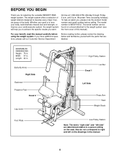
... your goal is WESY19512. The model number is to the weight system (see the front cover of this manual carefully before calling. ASSEMBLED DIMENSIONS: Height: 76 in the manual. 4 BEFORE YOU BEGIN Thank you , please note the product model number and serial number before using the... weight system. Whether your cardiovascular system, the weight system will help us assist you for selecting the versatile WEIDER® 8525 weight...
... your goal is WESY19512. The model number is to the weight system (see the front cover of this manual carefully before calling. ASSEMBLED DIMENSIONS: Height: 76 in the manual. 4 BEFORE YOU BEGIN Thank you , please note the product model number and serial number before using the... weight system. Whether your cardiovascular system, the weight system will help us assist you for selecting the versatile WEIDER® 8525 weight...
English Manual
Page 5
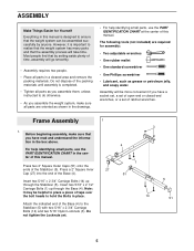
...tape over the bolt heads to ensure that the assembly process will go smoothly. • Assembly requires two people. • Place all parts in the box above. For help identifying small parts, use the PART IDENTIFICATION CHART in this manual is designed to hold the Bolts in place. ...parts, use the PART IDENTIFICATION CHART at the center of this manual. Press a 2" Square Inner 27 Cap (27) into the end of the Stabilizer (5). Most people find that you assemble the weight system, make sure that by anyone. Frame Assembly 1 1. Press two 2" Square Outer Caps (51) onto ...
...tape over the bolt heads to ensure that the assembly process will go smoothly. • Assembly requires two people. • Place all parts in the box above. For help identifying small parts, use the PART IDENTIFICATION CHART in this manual is designed to hold the Bolts in place. ...parts, use the PART IDENTIFICATION CHART at the center of this manual. Press a 2" Square Inner 27 Cap (27) into the end of the Stabilizer (5). Most people find that you assemble the weight system, make sure that by anyone. Frame Assembly 1 1. Press two 2" Square Outer Caps (51) onto ...
English Manual
Page 8
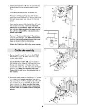
...the Retainers bend toward the Cover 55 Cap, as shown. 42 21 9 15 66 71 58 8 Lay the Cable in the same manner. 70 Cable Assembly 9. Lubricate both axles on each Arm. Make sure that the upper end of the bracket. 9 17 15 21 58 Bracket 12 4 10. Make sure...and that the end of the Arm with a 3/8" x 2" Bolt (12) and a 3/8" Nylon Locknut (21). Press a 1 3/4" Square Inner Cap (44) into the lower end of this manual to hold the Cable in the Front Upright (42) with a 3/8" x 3 3/4" Bolt (71), a 3/8" Washer (9), and a 3/8" Nylon Locknut (21). Make sure that the Cable is ...
...the Retainers bend toward the Cover 55 Cap, as shown. 42 21 9 15 66 71 58 8 Lay the Cable in the same manner. 70 Cable Assembly 9. Lubricate both axles on each Arm. Make sure that the upper end of the bracket. 9 17 15 21 58 Bracket 12 4 10. Make sure...and that the end of the Arm with a 3/8" x 2" Bolt (12) and a 3/8" Nylon Locknut (21). Press a 1 3/4" Square Inner Cap (44) into the lower end of this manual to hold the Cable in the Front Upright (42) with a 3/8" x 3 3/4" Bolt (71), a 3/8" Washer (9), and a 3/8" Nylon Locknut (21). Make sure that the Cable is ...


