
User Manual
Page 1
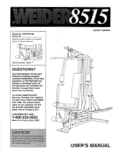
... through direct assistance from our factory. Read all precautions and instructions in the space above for futUre' reference. 8515 PATENT PENDING ) 00 00 0 USER'S MANUAL Write the serial number in this manual before using this manual for future reference. 0 0 0 Serial Number Decal QUESTIONS? CUSTOMER HOT LINE: 1-800-225-0653 Mon.-Fri., 6 a.m.-6 p.m. As a manufacturer, we are missing or damaged parts, we will provide immediate assistance, free...
... through direct assistance from our factory. Read all precautions and instructions in the space above for futUre' reference. 8515 PATENT PENDING ) 00 00 0 USER'S MANUAL Write the serial number in this manual before using this manual for future reference. 0 0 0 Serial Number Decal QUESTIONS? CUSTOMER HOT LINE: 1-800-225-0653 Mon.-Fri., 6 a.m.-6 p.m. As a manufacturer, we are missing or damaged parts, we will provide immediate assistance, free...
User Manual
Page 2
... OF CONTENTS LIMITED WARRANTY IMPORTANT PRECAUTIONS BEFORE YOU BEGIN ASSEMBLY HOW TO USE THE HOME GYM SYSTEM TROUBLESHOOTING AND MAINTENANCE CABLE DIAGRAM ORDERING REPLACEMENT PARTS 2 3 4 5 15 18 19 Back Cover Note: A PART IDENTIFICATION CHART and a PART LIST/EXPLODED DRAWING are attached to the center of this product to be pre-authorized by sufficient proof of purchase. ICON is limited in workmanship and material, under this warranty is limited to replacing or repairing, at ICON's option...
... OF CONTENTS LIMITED WARRANTY IMPORTANT PRECAUTIONS BEFORE YOU BEGIN ASSEMBLY HOW TO USE THE HOME GYM SYSTEM TROUBLESHOOTING AND MAINTENANCE CABLE DIAGRAM ORDERING REPLACEMENT PARTS 2 3 4 5 15 18 19 Back Cover Note: A PART IDENTIFICATION CHART and a PART LIST/EXPLODED DRAWING are attached to the center of this product to be pre-authorized by sufficient proof of purchase. ICON is limited in workmanship and material, under this warranty is limited to replacing or repairing, at ICON's option...
User Manual
Page 3
... an exercise that the cables remain on a level surface. Allow the cylinders to tip. If you are exercising, stop immediately and begin cooling down. Always stand on all parts often. inspect and tighten all of the pulleys. 8. Keep small children away from the home gym,system at all instructions before using the home gym system. Never release the press arm, butterfly arms, leg lever, lat bar or nylon strap while weights...
... an exercise that the cables remain on a level surface. Allow the cylinders to tip. If you are exercising, stop immediately and begin cooling down. Always stand on all parts often. inspect and tighten all of the pulleys. 8. Keep small children away from the home gym,system at all instructions before using the home gym system. Never release the press arm, butterfly arms, leg lever, lat bar or nylon strap while weights...
User Manual
Page 4
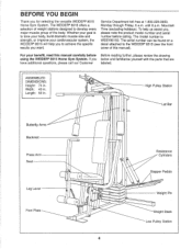
... your cardiovascular system, the WEIDER® 8515 will help us assist you want. ASSEMBLED DIMENSIONS: Height: 74 in . High Pulley Station Lat Bar Butterfly Arms Backrest Press Arm Seat Leg Lever Foot Plate O 0 0 O 0 4 Resistance Cylinders Stepper Pedals 0 Weight Pin Weight Stack Low Pulley Station The model number is to develop every major muscle group of this manual carefully before calling. If you for selecting the versatile WEIDER® 8515 Home Gym System. Length: 53 in...
... your cardiovascular system, the WEIDER® 8515 will help us assist you want. ASSEMBLED DIMENSIONS: Height: 74 in . High Pulley Station Lat Bar Butterfly Arms Backrest Press Arm Seat Leg Lever Foot Plate O 0 0 O 0 4 Resistance Cylinders Stepper Pedals 0 Weight Pin Weight Stack Low Pulley Station The model number is to develop every major muscle group of this manual carefully before calling. If you for selecting the versatile WEIDER® 8515 Home Gym System. Length: 53 in...
User Manual
Page 5
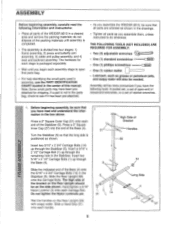
... as grease or petroleum jelly, and soapy water will be sure that parts bag. • For help identifying the small parts used in assembly, use the PART IDENTIFICATION CHART located in the center of the Base (4) onto the 5/16" x 2 3/4" Carriage Bolts (14) in the Stabilizer (5). Press a 2" Square Inner Cap (27) into four stages: 1) frame assembly, 2) press and butterfly arm assembly, 3) cable and pulley assembly, and 4) seat and backrest assembly. Hand-tighten...
... as grease or petroleum jelly, and soapy water will be sure that parts bag. • For help identifying the small parts used in assembly, use the PART IDENTIFICATION CHART located in the center of the Base (4) onto the 5/16" x 2 3/4" Carriage Bolts (14) in the Stabilizer (5). Press a 2" Square Inner Cap (27) into four stages: 1) frame assembly, 2) press and butterfly arm assembly, 3) cable and pulley assembly, and 4) seat and backrest assembly. Hand-tighten...

User Manual
Page 6
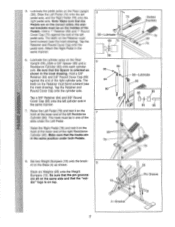
... Frame (55). Do not tighten the Nylon Locknuts yet. lL Attach the Top Frame (55) to the Rear Upright (56) with a 1/2" Metal Screw (77). Assemble the Right Pedal (not shown) in steps 1 through 3. 4. Attach the slotted end of the crossbar. Attach a Pedal Cover (81) to the 5/16" x 2 1/2" Carriage Bolt (1) in the Base (4). Press a 1 3/4" Square Inner Cap (44) into each Carriage Bolt. Press two 1 1/2" Bushings (82) into...
... Frame (55). Do not tighten the Nylon Locknuts yet. lL Attach the Top Frame (55) to the Rear Upright (56) with a 1/2" Metal Screw (77). Assemble the Right Pedal (not shown) in steps 1 through 3. 4. Attach the slotted end of the crossbar. Attach a Pedal Cover (81) to the 5/16" x 2 1/2" Carriage Bolt (1) in the Base (4). Press a 1 3/4" Square Inner Cap (44) into each Carriage Bolt. Press two 1 1/2" Bushings (82) into...
User Manual
Page 7
... Round 2 Cover Cap (85) onto the left pedal axle, and the Right Pedal (78) onto the right pedal axle. Make sure that the Spacer is on the LLI hook at the lower end of the right Resistance Cylinder (80). The teeth on the Rear Upright (56).,,Slide a 5/8" Spacer (86) and a Resistance Cylinder (80...on the Base (4) as shown in the same manner. 6. Set two Weight Bumpers (19) onto the brack- 8 et on the Retainer must be on the Rear Upright (56). Attach the Right Pedal in the inset drawing. Slide the Left Pedal (79) onto the left cylinder axle in the same position...
... Round 2 Cover Cap (85) onto the left pedal axle, and the Right Pedal (78) onto the right pedal axle. Make sure that the Spacer is on the LLI hook at the lower end of the right Resistance Cylinder (80). The teeth on the Rear Upright (56).,,Slide a 5/8" Spacer (86) and a Resistance Cylinder (80...on the Base (4) as shown in the same manner. 6. Set two Weight Bumpers (19) onto the brack- 8 et on the Retainer must be on the Rear Upright (56). Attach the Right Pedal in the inset drawing. Slide the Left Pedal (79) onto the left cylinder axle in the same position...
User Manual
Page 8
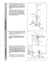
... 9 end of the Weight Tube (63). The 1" x 7/8" Plastic Bushings should fit on the Weight Tube are sitting in the pin grooves in the top Weight. Lubricate the 3/8" x 8" Bolt (59). Be sure that the holes in front of the right Weight Guide (62) as shown. Be sure that the Pulley Bracket (20) is in the Weight Guides are on the Press Frame (17). Be...
... 9 end of the Weight Tube (63). The 1" x 7/8" Plastic Bushings should fit on the Weight Tube are sitting in the pin grooves in the top Weight. Lubricate the 3/8" x 8" Bolt (59). Be sure that the holes in front of the right Weight Guide (62) as shown. Be sure that the Pulley Bracket (20) is in the Weight Guides are on the Press Frame (17). Be...
User Manual
Page 9
... the lower end of each Arm with two 5/16" x 2 1/2" Bolts (22) and two 5/16" Nylon Locknuts (3). Lubricate both axles on the Retainers bend toward the Cover Cap, as shown in the inset drawing. Wet the handle of the Right Arm is behind the indicated bracket on the Top Frame (55). tion of the "V" Pulley (6) to one Press Arm (46...
... the lower end of each Arm with two 5/16" x 2 1/2" Bolts (22) and two 5/16" Nylon Locknuts (3). Lubricate both axles on the Retainers bend toward the Cover Cap, as shown in the inset drawing. Wet the handle of the Right Arm is behind the indicated bracket on the Top Frame (55). tion of the "V" Pulley (6) to one Press Arm (46...
User Manual
Page 10
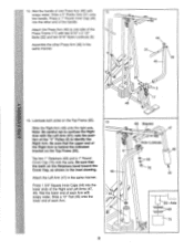
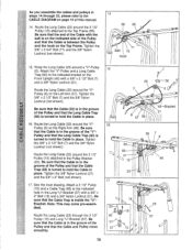
... "V"- Route the Long Cable (23) through 22, please refer to hold the Cable in place. As you assemble the cables and pulleys in steps 14 through the 3 1/2" Pulley (15) and Long "U"-Bracket (57). Note: This may come pre-assembled. Tighten the 3/8" x 2 1/2" Bolt (7) and the 3/8" Nylon Locknut (not shown). Tighten the 3/8" x 3 3/4" Bolt (71) and the 3/8" Nylon Locknut (not shown). 15. ILI Pulley (6) on the Left Arm...
... "V"- Route the Long Cable (23) through 22, please refer to hold the Cable in place. As you assemble the cables and pulleys in steps 14 through the 3 1/2" Pulley (15) and Long "U"-Bracket (57). Note: This may come pre-assembled. Tighten the 3/8" x 2 1/2" Bolt (7) and the 3/8" Nylon Locknut (not shown). Tighten the 3/8" x 3 3/4" Bolt (71) and the 3/8" Nylon Locknut (not shown). 15. ILI Pulley (6) on the Left Arm...
User Manual
Page 11
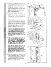
... pre-assembled. Tighten the 3/8" Nylon Locknut (21) and 3/8" x 3 3/4" Bolt CCI (not shown). 0 20. Be sure that the Cable Trap (not shown) is turned to hold the Cable in the Front Upright (42). Tighten the 3/8" Nylon Locknut (21) and 3/8" x 3 3/4" Bolt (not shown). 21. Route the Short Cable (58) under the 3 1/2" Pulley (15) attached to the lower hole in place and that the Cable is routed around the Pulley...
... pre-assembled. Tighten the 3/8" Nylon Locknut (21) and 3/8" x 3 3/4" Bolt CCI (not shown). 0 20. Be sure that the Cable Trap (not shown) is turned to hold the Cable in the Front Upright (42). Tighten the 3/8" Nylon Locknut (21) and 3/8" x 3 3/4" Bolt (not shown). 21. Route the Short Cable (58) under the 3 1/2" Pulley (15) attached to the lower hole in place and that the Cable is routed around the Pulley...
User Manual
Page 12
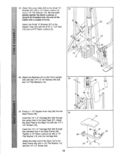
... hole in the Seat Frame (36). Attach the Small "U"-Bracket (67) to the Seat (13) with the 5/16" x 1 3/4" Bolt (72) and a 5/16" Nylon Locknut (3). 3 10 2 23 72 67 63 0 23. Attach the Seat Plate to the Weight Tube (63) with two 1/4" x 1/2" Screws (18). Tighten a 1/4" Nylon Locknut (2) with a 1/4" Nylon Locknut (2) and a 1/4" Flat Washer (10). 22. Attach the Long Cable (23) to the...
... hole in the Seat Frame (36). Attach the Small "U"-Bracket (67) to the Seat (13) with the 5/16" x 1 3/4" Bolt (72) and a 5/16" Nylon Locknut (3). 3 10 2 23 72 67 63 0 23. Attach the Seat Plate to the Weight Tube (63) with two 1/4" x 1/2" Screws (18). Tighten a 1/4" Nylon Locknut (2) with a 1/4" Nylon Locknut (2) and a 1/4" Flat Washer (10). 22. Attach the Long Cable (23) to the...
User Manual
Page 13
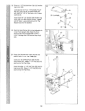
...Leg Lever (29). Press a 1 1/2" Square Inner Cap (32) into the Leg Lever (29). Tighten a 5/16" Nylon Locknut (3) with a 5/16" x 2 3/4" Carriage Bolt (14) and the Seat Knob (40). 4 40 36 36 29 8 3 42Pin 27. Slide a 5 1/2" Pad (30) onto each end of the Pad Tube. Attach the Leg Lever (29) to the Front Upright... with a 5/16" Flat Washer (8) onto the Eyebolt. z 33-Lubricate 35 26. Rest the Seat Frame (36) on the indicated pin in the Front Upright (42). Lubricate the 5/16" x 2 1/4" Bolt (33). Press 3/4" Round Inner ...
...Leg Lever (29). Press a 1 1/2" Square Inner Cap (32) into the Leg Lever (29). Tighten a 5/16" Nylon Locknut (3) with a 5/16" x 2 3/4" Carriage Bolt (14) and the Seat Knob (40). 4 40 36 36 29 8 3 42Pin 27. Slide a 5 1/2" Pad (30) onto each end of the Pad Tube. Attach the Leg Lever (29) to the Front Upright... with a 5/16" Flat Washer (8) onto the Eyebolt. z 33-Lubricate 35 26. Rest the Seat Frame (36) on the indicated pin in the Front Upright (42). Lubricate the 5/16" x 2 1/4" Bolt (33). Press 3/4" Round Inner ...
User Manual
Page 14
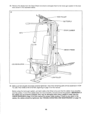
... TO USE THE HOME GYM SYSTEM, beginning on page 15 of the cables does not move smoothly over the pulleys. If one of this manual for proper cable routing. If there is used. 28. IMPORTANT: If the cables are not properly installed, they may be explained in the illustration below. 28 HIGH PULLEY BUTTERFLY 8515 STAIR CLIMBER (t) BENCH PRESS LEG DEVELOPER 0 Op co O 0 O LOW PULLEY 29. See the CABLE DIAGRAM...
... TO USE THE HOME GYM SYSTEM, beginning on page 15 of the cables does not move smoothly over the pulleys. If one of this manual for proper cable routing. If there is used. 28. IMPORTANT: If the cables are not properly installed, they may be explained in the illustration below. 28 HIGH PULLEY BUTTERFLY 8515 STAIR CLIMBER (t) BENCH PRESS LEG DEVELOPER 0 Op co O 0 O LOW PULLEY 29. See the CABLE DIAGRAM...
User Manual
Page 15
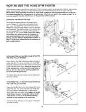
... USE THE HOME GYM SYSTEM The instructions below describe how each part of the weight stack, insert a Weight Pin (26) under the desired Weight (25). IMPORTANT: When attaching the lat bar or nylon strap, make sure that the attachments are in the correct starting position for the exercise to the Short Cable (58) with two Cable Clips. ATTACHING THE LAT BAR OR NYLON STRAP TO THE LOW PULLEY STATION Attach the Lat Bar (54) to be attached...
... USE THE HOME GYM SYSTEM The instructions below describe how each part of the weight stack, insert a Weight Pin (26) under the desired Weight (25). IMPORTANT: When attaching the lat bar or nylon strap, make sure that the attachments are in the correct starting position for the exercise to the Short Cable (58) with two Cable Clips. ATTACHING THE LAT BAR OR NYLON STRAP TO THE LOW PULLEY STATION Attach the Lat Bar (54) to be attached...
User Manual
Page 16
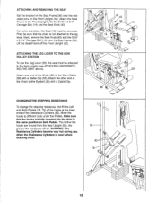
... . CHANGING THE STEPPING RESISTANCE To change the stepping resistance, first lift the Left and Right Pedals (78, 79) off the Front Upright (42). Lift the Seat Frame off the hooks at the lower ends of the Resistance Cylinders (80). ATTACHING THE LEG LEVER TO THE LOW PULLEY STATION To use . Make sure that the chain is not attached to the Short Cable (58) with the 5/16" x 2 3/4" Carriage Bolt...
... . CHANGING THE STEPPING RESISTANCE To change the stepping resistance, first lift the Left and Right Pedals (78, 79) off the Front Upright (42). Lift the Seat Frame off the hooks at the lower ends of the Resistance Cylinders (80). ATTACHING THE LEG LEVER TO THE LOW PULLEY STATION To use . Make sure that the chain is not attached to the Short Cable (58) with the 5/16" x 2 3/4" Carriage Bolt...
User Manual
Page 17
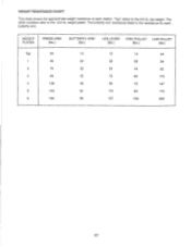
WEIGHT PLATES PRESS ARM (lbs.) BUTTERFLY ARM (lbs.) LEG LEVER HIGH PULLEY LOW PULLEY (lbs.) (lbs.) (lbs.) Top 20 1 45 2 70 3 99 4 128 5 153 6 184 10 15 14 24 22 36 28 54 33 54 44 82 42 75 60 115 48 96 72 147 60 115 90 175 69 137 103 209 17 weight plates. top weight. The other numbers refer to the 6.5 lb. "Top" refers to the 12.5 lb. The butterfly arm resistance listed is the resistance for each station. WEIGHT RESISTANCE CHART This chart shows the approximate weight resistance at each butterfly arm.
WEIGHT PLATES PRESS ARM (lbs.) BUTTERFLY ARM (lbs.) LEG LEVER HIGH PULLEY LOW PULLEY (lbs.) (lbs.) (lbs.) Top 20 1 45 2 70 3 99 4 128 5 153 6 184 10 15 14 24 22 36 28 54 33 54 44 82 42 75 60 115 48 96 72 147 60 115 90 175 69 137 103 209 17 weight plates. top weight. The other numbers refer to the 6.5 lb. "Top" refers to the 12.5 lb. The butterfly arm resistance listed is the resistance for each station. WEIGHT RESISTANCE CHART This chart shows the approximate weight resistance at each butterfly arm.
User Manual
Page 18
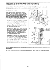
... Cable and Pulley move smoothly. 66 57 21 12 2 58 Note: If a cable tends to the other hole in the cables before tightening the cables. Remove the 3/8" Nylon Locknut (21) and the 3/8" x 2" Bolt (12) from the Long "U"-Bracket (57). TROUBLE-SHOOTING AND MAINTENANCE Inspect and tighten all parts often and replace any worn parts immediately. IMPORTANT: The Weight Pin (26) must be removed from the Weight Tube (63). The home gym...
... Cable and Pulley move smoothly. 66 57 21 12 2 58 Note: If a cable tends to the other hole in the cables before tightening the cables. Remove the 3/8" Nylon Locknut (21) and the 3/8" x 2" Bolt (12) from the Long "U"-Bracket (57). TROUBLE-SHOOTING AND MAINTENANCE Inspect and tighten all parts often and replace any worn parts immediately. IMPORTANT: The Weight Pin (26) must be removed from the Weight Tube (63). The home gym...
User Manual
Page 19
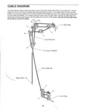
... correctly routed, the home gym system will not come off the pulleys. Examine all cable traps; CABLE DIAGRAM The cable diagram below shows the proper routing of the Short Cable (58) and the Long Cable (23). The starting and ending points for each cable are labeled. Be sure the the cable traps do not touch or bind the cables. 1 -High Pulley 7 3 5 4 Long Cable (23) 6 5-Long "U"-Bracket Weight Stack -8 Short Cable...
... correctly routed, the home gym system will not come off the pulleys. Examine all cable traps; CABLE DIAGRAM The cable diagram below shows the proper routing of the Short Cable (58) and the Long Cable (23). The starting and ending points for each cable are labeled. Be sure the the cable traps do not touch or bind the cables. 1 -High Pulley 7 3 5 4 Long Cable (23) 6 5-Long "U"-Bracket Weight Stack -8 Short Cable...


