
User Manual
Page 10
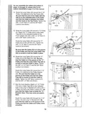
...of this manual. 14. Tighten the 3/8" x 3 3/4" Bolt (71) and the 3/8" Nylon Locknut (not shown). 15. Route the Long Cable (23) around the "V"Pulley (6) on page 19 of the Pulley and that the Cable and Pulley move smoothly. 14 55 23 , Ball 71 15 Hook til 15 23 7 ,.,, / 7 r - 50 (...17 , Q 15 23/a.. . 15 23 66 57 217 ' • • 57 12 / 10 Route the Long Cable (23) around the 3 1/2" Pulley (15) attached to the CABLE DIAGRAM on the Left Arm (47). Route the Long Cable (23) through 22, please refer to the Top Frame (55). Tighten the 3/8" Nylon Locknut (21) ...
...of this manual. 14. Tighten the 3/8" x 3 3/4" Bolt (71) and the 3/8" Nylon Locknut (not shown). 15. Route the Long Cable (23) around the "V"Pulley (6) on page 19 of the Pulley and that the Cable and Pulley move smoothly. 14 55 23 , Ball 71 15 Hook til 15 23 7 ,.,, / 7 r - 50 (...17 , Q 15 23/a.. . 15 23 66 57 217 ' • • 57 12 / 10 Route the Long Cable (23) around the 3 1/2" Pulley (15) attached to the CABLE DIAGRAM on the Left Arm (47). Route the Long Cable (23) through 22, please refer to the Top Frame (55). Tighten the 3/8" Nylon Locknut (21) ...
User Manual
Page 11
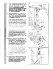
...Locknut. Tighten the 3/8" x 2" Bolt (12) and the 3/8" Nylon Locknut (21). (Note: This Pulley is in place and that the Cable is routed around the Pulley as shown. Reattach the Pulley with the 5/8" x 9/16" Spacer (73) between the Pulley and the crossbar on the Press... the 3/8" Nylon Locknut (21) and 3/8" x 3 1/2" Bolt (not shown). Tighten the 3/8" Nylon Locknut (21) and 3/8" x 3 3/4" Bolt CCI (not shown). 0 20. Route the Short Cable (58) around the 3 1/2" Pulley (15) attached to the upper hole in the Press Frame (17). It has been shown disassembled for easy part identification...
...Locknut. Tighten the 3/8" x 2" Bolt (12) and the 3/8" Nylon Locknut (21). (Note: This Pulley is in place and that the Cable is routed around the Pulley as shown. Reattach the Pulley with the 5/8" x 9/16" Spacer (73) between the Pulley and the crossbar on the Press... the 3/8" Nylon Locknut (21) and 3/8" x 3 1/2" Bolt (not shown). Tighten the 3/8" Nylon Locknut (21) and 3/8" x 3 3/4" Bolt CCI (not shown). 0 20. Route the Short Cable (58) around the 3 1/2" Pulley (15) attached to the upper hole in the Press Frame (17). It has been shown disassembled for easy part identification...
User Manual
Page 14
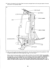
...is any slack in the illustration below. 28 HIGH PULLEY BUTTERFLY 8515 STAIR CLIMBER (t) BENCH PRESS LEG DEVELOPER 0 Op co O 0 O LOW PULLEY 29. If there is used. If one of this manual for proper cable routing. IMPORTANT: If the cables are not properly installed, they may be sure that all ...parts have been properly tightened. Before using the home gym system, pull each cable a few times to the home gym system in the locations...
...is any slack in the illustration below. 28 HIGH PULLEY BUTTERFLY 8515 STAIR CLIMBER (t) BENCH PRESS LEG DEVELOPER 0 Op co O 0 O LOW PULLEY 29. If there is used. If one of this manual for proper cable routing. IMPORTANT: If the cables are not properly installed, they may be sure that all ...parts have been properly tightened. Before using the home gym system, pull each cable a few times to the home gym system in the locations...
User Manual
Page 19
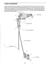
...-Low Pulley 19 The numbers show the correct route for each cable. the cable traps should be sure that the cables will not function properly and damage may occur. Use the diagram to be positioned so that the two cables have not been correctly routed, the home gym system will not come off... the pulleys. The starting and ending points for each cable are labeled. CABLE DIAGRAM The cable diagram below shows the proper routing of the Short Cable (58) and the Long Cable (23). If the cables have been...
...-Low Pulley 19 The numbers show the correct route for each cable. the cable traps should be sure that the cables will not function properly and damage may occur. Use the diagram to be positioned so that the two cables have not been correctly routed, the home gym system will not come off... the pulleys. The starting and ending points for each cable are labeled. CABLE DIAGRAM The cable diagram below shows the proper routing of the Short Cable (58) and the Long Cable (23). If the cables have been...


