Operating Instructions
Page 4
... and data-enhanced television services may be blurred or show poor color. This TV is a U.S. Dolby and the double-D symbol are trademarks of SRS Labs, Inc. SONY APPLIANCE MODEL NO: KDF-E55A20 KDF-E60A20 SONY TV STAND MODEL NO: SU-GW12 Replacement Parts See page 4 under U.S. ENERGY... STAR® is manufactured under license from SRS Labs, Inc. 2 BBE and BBE Symbol are not of a reflective material. ❑ See page 12 & 13 for replacement lamp....
... and data-enhanced television services may be blurred or show poor color. This TV is a U.S. Dolby and the double-D symbol are trademarks of SRS Labs, Inc. SONY APPLIANCE MODEL NO: KDF-E55A20 KDF-E60A20 SONY TV STAND MODEL NO: SU-GW12 Replacement Parts See page 4 under U.S. ENERGY... STAR® is manufactured under license from SRS Labs, Inc. 2 BBE and BBE Symbol are not of a reflective material. ❑ See page 12 & 13 for replacement lamp....
Operating Instructions
Page 6
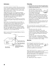
... 810-21) Ground clamps Power service grounding electrode system (NEC Art 250 Part H) Cleaning ❑ Clean the rear cover area of the TV with a solution of the TV. Unauthorized substitutions may scratch the screen's coating. Antenna Grounding According to the NEC Refer to section 54-300 of...To prevent screen damage, clean the screen as follows: ❑ Clean the screen with such power lines or circuits. See "Replacing the Lamp" on the Screen Surface The screen surface has a special coating to qualified service personnel. Be sure the antenna system is installed, follow the...
... 810-21) Ground clamps Power service grounding electrode system (NEC Art 250 Part H) Cleaning ❑ Clean the rear cover area of the TV with a solution of the TV. Unauthorized substitutions may scratch the screen's coating. Antenna Grounding According to the NEC Refer to section 54-300 of...To prevent screen damage, clean the screen as follows: ❑ Clean the screen with such power lines or circuits. See "Replacing the Lamp" on the Screen Surface The screen surface has a special coating to qualified service personnel. Be sure the antenna system is installed, follow the...
Operating Instructions
Page 7
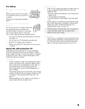
... bulb may pop inside the lamp unit. (see page 12). ❑ Do not carry the TV holding the speaker grill. ❑ Hold the TV tightly when carrying it. ❑ Before carrying the TV, disconnect any accessories or cables. About the LCD projection TV Although the LCD projection TV is designed to contain all ... noise level is inherent in a manner other strong illumination shines on the screen, part of persons (see "Replacing the Lamp" on page 76) ❑ When the lamp eventually burns out, you may hear the noise of fan running, depending on the placement of the LCD projection TV.
... bulb may pop inside the lamp unit. (see page 12). ❑ Do not carry the TV holding the speaker grill. ❑ Hold the TV tightly when carrying it. ❑ Before carrying the TV, disconnect any accessories or cables. About the LCD projection TV Although the LCD projection TV is designed to contain all ... noise level is inherent in a manner other strong illumination shines on the screen, part of persons (see "Replacing the Lamp" on page 76) ❑ When the lamp eventually burns out, you may hear the noise of fan running, depending on the placement of the LCD projection TV.
Operating Instructions
Page 8
...Sony TV Presenting the Sony TV 8 Package Contents 8 Features 8 Enjoying Your TV 10 Notes on the TV 10 Screen 10 Indicators 11 Projection Lamp 11 Installing the TV 12 Carrying Your TV 12 Take Precaution during Installation 13 To Prevent the TV from Falling 13 When Installing Your TV Against a Wall .....13 Recommended Viewing Area 13 TV... Overview 56 Accessing the Video Settings 58 Selecting Video Options 58 Accessing the Audio Settings 60 Selecting Audio Options 60 Accessing the Screen Settings 62 Selecting Screen Options 62 Accessing the Channel Settings 64 Selecting ...
...Sony TV Presenting the Sony TV 8 Package Contents 8 Features 8 Enjoying Your TV 10 Notes on the TV 10 Screen 10 Indicators 11 Projection Lamp 11 Installing the TV 12 Carrying Your TV 12 Take Precaution during Installation 13 To Prevent the TV from Falling 13 When Installing Your TV Against a Wall .....13 Recommended Viewing Area 13 TV... Overview 56 Accessing the Video Settings 58 Selecting Video Options 58 Accessing the Audio Settings 60 Selecting Audio Options 60 Accessing the Screen Settings 62 Selecting Screen Options 62 Accessing the Channel Settings 64 Selecting ...
Operating Instructions
Page 9
Accessing the Setup Settings 70 Selecting Setup Options 70 Programming Caption Vision 72 Accessing the Applications Settings 73 Selecting Applications Options 73 Other Information Overview 75 Contacting Sony 75 Replacing the Lamp 76 How to Replace the Lamp 76 Troubleshooting 80 Remote Control 80 CableCARDTM Device 80 Video 81 Audio 82 Channels 82 General 83 Specifications 84 Optional Accessories 85 Index Index 87 7
Accessing the Setup Settings 70 Selecting Setup Options 70 Programming Caption Vision 72 Accessing the Applications Settings 73 Selecting Applications Options 73 Other Information Overview 75 Contacting Sony 75 Replacing the Lamp 76 How to Replace the Lamp 76 Troubleshooting 80 Remote Control 80 CableCARDTM Device 80 Video 81 Audio 82 Channels 82 General 83 Specifications 84 Optional Accessories 85 Index Index 87 7
Operating Instructions
Page 13
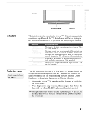
... screen goes dark. As with a new flashes. POWER (red) flashing The lamp cover is a change in the diagram above. Introducing the Sony TV Introducing the Sony TV Screen Projection lamp POWER LAMP TIMER POWER Indicators Indicators Projection Lamp How to replace the lamp, see page 14). one of your TV, it has lifespan and needs to let you know that it requires...
... screen goes dark. As with a new flashes. POWER (red) flashing The lamp cover is a change in the diagram above. Introducing the Sony TV Introducing the Sony TV Screen Projection lamp POWER LAMP TIMER POWER Indicators Indicators Projection Lamp How to replace the lamp, see page 14). one of your TV, it has lifespan and needs to let you know that it requires...
Operating Instructions
Page 16
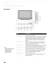
...light source has burned out. For details, see "Contacting Sony" on . For details, see "Replacing the Lamp" on /off the TV. Item 1 POWER 2 POWER LED 3 TIMER LED 4 LAMP LED 5 (IR) Infrared Receiver 6 CHANNEL +/- 7 VOLUME +/- 8 TV/VIDEO Description Press to scan through channels, press and ... be affected. Press to turn on page 76. To scan quickly through channels. Introducing the Sony TV TV Front Panel and Connectors Front Panel POWER LAMP TIMER POWER POWER LAMP TIMER POWER CHANNEL 3 # VOLUME 3 # TV/VIDEO 6 7 8 5432 1 z The CHANNEL + button has a tactile dot. Use the...
...light source has burned out. For details, see "Contacting Sony" on . For details, see "Replacing the Lamp" on /off the TV. Item 1 POWER 2 POWER LED 3 TIMER LED 4 LAMP LED 5 (IR) Infrared Receiver 6 CHANNEL +/- 7 VOLUME +/- 8 TV/VIDEO Description Press to scan through channels, press and ... be affected. Press to turn on page 76. To scan quickly through channels. Introducing the Sony TV TV Front Panel and Connectors Front Panel POWER LAMP TIMER POWER POWER LAMP TIMER POWER CHANNEL 3 # VOLUME 3 # TV/VIDEO 6 7 8 5432 1 z The CHANNEL + button has a tactile dot. Use the...
Operating Instructions
Page 17
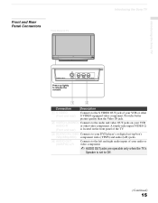
... Sony TV Front and Rear Panel Connectors Front Panel of TV Introducing the Sony TV POWER LAMP TIMER POWER VIDEO 2 INPUT S VIDEO VIDEO L (MONO) R AUDIO Press up lightly to release the console 1 2 Connection Description 1 S VIDEO (Front and rear) Connects to the audio and video OUT jacks on the front panel of the TV....Continued) 15 Connects to the S VIDEO OUT jack of your audio or video component. ✍ AUDIO OUT jacks are operable only when the TV's Speaker is set -top box's 720p/480p/480i) component video (YPbPr) and audio (L/R) jacks. 4 AUDIO OUT (VAR/FIX) L/R Connects...
... Sony TV Front and Rear Panel Connectors Front Panel of TV Introducing the Sony TV POWER LAMP TIMER POWER VIDEO 2 INPUT S VIDEO VIDEO L (MONO) R AUDIO Press up lightly to release the console 1 2 Connection Description 1 S VIDEO (Front and rear) Connects to the audio and video OUT jacks on the front panel of the TV....Continued) 15 Connects to the S VIDEO OUT jack of your audio or video component. ✍ AUDIO OUT jacks are operable only when the TV's Speaker is set -top box's 720p/480p/480i) component video (YPbPr) and audio (L/R) jacks. 4 AUDIO OUT (VAR/FIX) L/R Connects...
Operating Instructions
Page 77
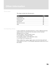
... Canadian residents: 1-877-899-SONY (7669) or visit: http://www.sonystyle.ca/tv/ Before calling Sony customer support, please write down the model and serial numbers of your Sony television, please call our Customer Information Services Center. Other Information Overview This chapter includes the following topics: Topic Contacting Sony Replacing the Lamp Troubleshooting Specifications Optional Accessories...
... Canadian residents: 1-877-899-SONY (7669) or visit: http://www.sonystyle.ca/tv/ Before calling Sony customer support, please write down the model and serial numbers of your Sony television, please call our Customer Information Services Center. Other Information Overview This chapter includes the following topics: Topic Contacting Sony Replacing the Lamp Troubleshooting Specifications Optional Accessories...
Operating Instructions
Page 78
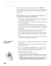
... sound. Use of the used lamps follow the instructions below. ❑ Use a Sony XL-2200 replacement lamp (not supplied) for any purpose other than replacement. Do not touch the lamp receptable once the lamp has been removed. ❑ When the lamp eventually burns out, you may... reduce picture quality or lamp life. 76 How to Replace the Lamp 1 Turn off .) 2 Wait at least 30 minutes after removing the lamp. Doing so may damage the TV. ❑ Do not remove the lamp for replacement. Other Information Replacing the Lamp The projection lamp, which illuminates the picture...
... sound. Use of the used lamps follow the instructions below. ❑ Use a Sony XL-2200 replacement lamp (not supplied) for any purpose other than replacement. Do not touch the lamp receptable once the lamp has been removed. ❑ When the lamp eventually burns out, you may... reduce picture quality or lamp life. 76 How to Replace the Lamp 1 Turn off .) 2 Wait at least 30 minutes after removing the lamp. Doing so may damage the TV. ❑ Do not remove the lamp for replacement. Other Information Replacing the Lamp The projection lamp, which illuminates the picture...
Operating Instructions
Page 79
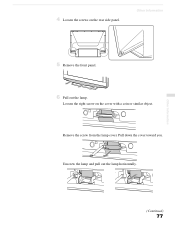
Remove the screw from the lamp cover. Pull down the cover toward you. Other Information 5 Remove the front panel. STD/DUO PRO POWER 6 Pull out the lamp. Other Information (Continued) 77 Unscrew the lamp and pull out the lamp horizontally. 4 Loosen the screws on the cover with a coin or similar object. Loosen the right screw on the rear side panel.
Remove the screw from the lamp cover. Pull down the cover toward you. Other Information 5 Remove the front panel. STD/DUO PRO POWER 6 Pull out the lamp. Other Information (Continued) 77 Unscrew the lamp and pull out the lamp horizontally. 4 Loosen the screws on the cover with a coin or similar object. Loosen the right screw on the rear side panel.
Operating Instructions
Page 80
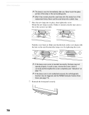
...on . STD/DUO PRO POWER 78 In such a case, remove the screw, insert it has cooled, place the used lamp into a plastic bag. 7 Place the new lamp into the empty box of the lamp or the surrounding parts. ✍ After it correctly and then tighten the screw completely (see "Indicators" on page 11...). ✍ If the lamp cover is not reattached securely, the self-diagnostic function may cause a fire or the screen to go dark. Failure to mount correctly may be ...
...on . STD/DUO PRO POWER 78 In such a case, remove the screw, insert it has cooled, place the used lamp into a plastic bag. 7 Place the new lamp into the empty box of the lamp or the surrounding parts. ✍ After it correctly and then tighten the screw completely (see "Indicators" on page 11...). ✍ If the lamp cover is not reattached securely, the self-diagnostic function may cause a fire or the screen to go dark. Failure to mount correctly may be ...
Operating Instructions
Page 81
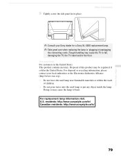
...: This product contains mercury. For disposal or recycling information, please contact your Sony dealer for a Sony XL-2200 replacement lamp. ✍ Take great care when replacing the lamp or plugging in the United States. Rough handling may cause the lamp to fall, damaging the TV, the TV stand and/or the floor. Doing so may cause the...
...: This product contains mercury. For disposal or recycling information, please contact your Sony dealer for a Sony XL-2200 replacement lamp. ✍ Take great care when replacing the lamp or plugging in the United States. Rough handling may cause the lamp to fall, damaging the TV, the TV stand and/or the floor. Doing so may cause the...
Operating Instructions
Page 85
... Press RESET menu option while in gray, this may indicate the TV needs service. TIMER is set to temporarily unblock channels. Contact your cable provider for both KDF-E55A20 and KDF-E60A20). to VCR The replacement lamp does not ❏ The screw of your previous password; Digital ...cable box does not work with your VCR. Lost password ❏ In the password screen (see page 60). Take out the screw, ...
... Press RESET menu option while in gray, this may indicate the TV needs service. TIMER is set to temporarily unblock channels. Contact your cable provider for both KDF-E55A20 and KDF-E60A20). to VCR The replacement lamp does not ❏ The screw of your previous password; Digital ...cable box does not work with your VCR. Lost password ❏ In the password screen (see page 60). Take out the screw, ...
Operating Instructions
Page 86
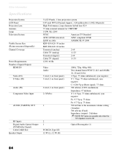
...Rectangular (1) PCMCIA Type I/II 12 W (L), 12 W (R) 84 Other Information Specifications Projection System LCD Panel Projection Lens Antenna Lamp Television System Visible Screen Size (Picture measured diagonally) Channel Coverage Power Requirements Number of ...projection system 0.87 inch TFT LCD panel Approx. 3.28 million dots (1,042,168 pixels) High Performance, large diameter hybrid lens F2.4 75 ohm external terminal for VHF/UHF 132W, XL-2200 NTSC American TV Standard ATSC (8VSB terrestrial) ATSC compliant 8VSB QAM on cable ANSI/SCTE 07 2000 KDF-E55A20: 55 inches KDF-E60A20: 60...
...Rectangular (1) PCMCIA Type I/II 12 W (L), 12 W (R) 84 Other Information Specifications Projection System LCD Panel Projection Lens Antenna Lamp Television System Visible Screen Size (Picture measured diagonally) Channel Coverage Power Requirements Number of ...projection system 0.87 inch TFT LCD panel Approx. 3.28 million dots (1,042,168 pixels) High Performance, large diameter hybrid lens F2.4 75 ohm external terminal for VHF/UHF 132W, XL-2200 NTSC American TV Standard ATSC (8VSB terrestrial) ATSC compliant 8VSB QAM on cable ANSI/SCTE 07 2000 KDF-E55A20: 55 inches KDF-E60A20: 60...

Operating Instructions
Page 87
...inches) (1,456 × 943 × 491 mm) KDF-E60A20: (62 × 39 5/8 × 20 1/2 inches) (1,574 × 1,005 × 518 mm) Mass KDF-E55A20: 92.5 lb (42 kg) KDF-E60A20: 101.5 lb (46.1 kg) Supplied Accessories Remote ...Control RM-YD002 AA (R6) Batteries 2 supplied for remote control Design and specifications are approximate. Optional Accessories ❑ HDMI cable ❑ Component video cable ❑ S VIDEO cable ❑ A/V cable ❑ Audio cable ❑ Optical cable ❑ TV Stand: SU-GW12 ❑ Lamp...
...inches) (1,456 × 943 × 491 mm) KDF-E60A20: (62 × 39 5/8 × 20 1/2 inches) (1,574 × 1,005 × 518 mm) Mass KDF-E55A20: 92.5 lb (42 kg) KDF-E60A20: 101.5 lb (46.1 kg) Supplied Accessories Remote ...Control RM-YD002 AA (R6) Batteries 2 supplied for remote control Design and specifications are approximate. Optional Accessories ❑ HDMI cable ❑ Component video cable ❑ S VIDEO cable ❑ A/V cable ❑ Audio cable ❑ Optical cable ❑ TV Stand: SU-GW12 ❑ Lamp...
Operating Instructions
Page 89
... Video 59 Alternate Audio 49 Alternate Video 49 ANT button 42 Applications Menu 73 Audio Menu 60 Audio receiver, connecting 39 Audio setting 56 B Balance, adjusting 60 Bass, adjusting 60 Batteries, inserting in remote 41 Bilingual audio 61 Brightness, adjusting 58 C Cable with VCR, connecting 32 Cable box connecting ... GUIDE button 42, 48 Guide menu 49 H Hue, adjusting 58 I Inputs, labeling 70 Installation of the projection TV 19-39 J JUMP button 42, 51 L Label Channels 30, 65 video inputs 70 Lamp, replacing 76-79 M MENU button 43 Menus Parent 66 Screen 62 Setup 70 Mode Custom 58 Standard 58...
... Video 59 Alternate Audio 49 Alternate Video 49 ANT button 42 Applications Menu 73 Audio Menu 60 Audio receiver, connecting 39 Audio setting 56 B Balance, adjusting 60 Bass, adjusting 60 Batteries, inserting in remote 41 Bilingual audio 61 Brightness, adjusting 58 C Cable with VCR, connecting 32 Cable box connecting ... GUIDE button 42, 48 Guide menu 49 H Hue, adjusting 58 I Inputs, labeling 70 Installation of the projection TV 19-39 J JUMP button 42, 51 L Label Channels 30, 65 video inputs 70 Lamp, replacing 76-79 M MENU button 43 Menus Parent 66 Screen 62 Setup 70 Mode Custom 58 Standard 58...


